4-100
Maintenance and inspection procedures
5Maintenance and Inspection
5.3.2 Installing/removing the cover
(1) RV-2FR series
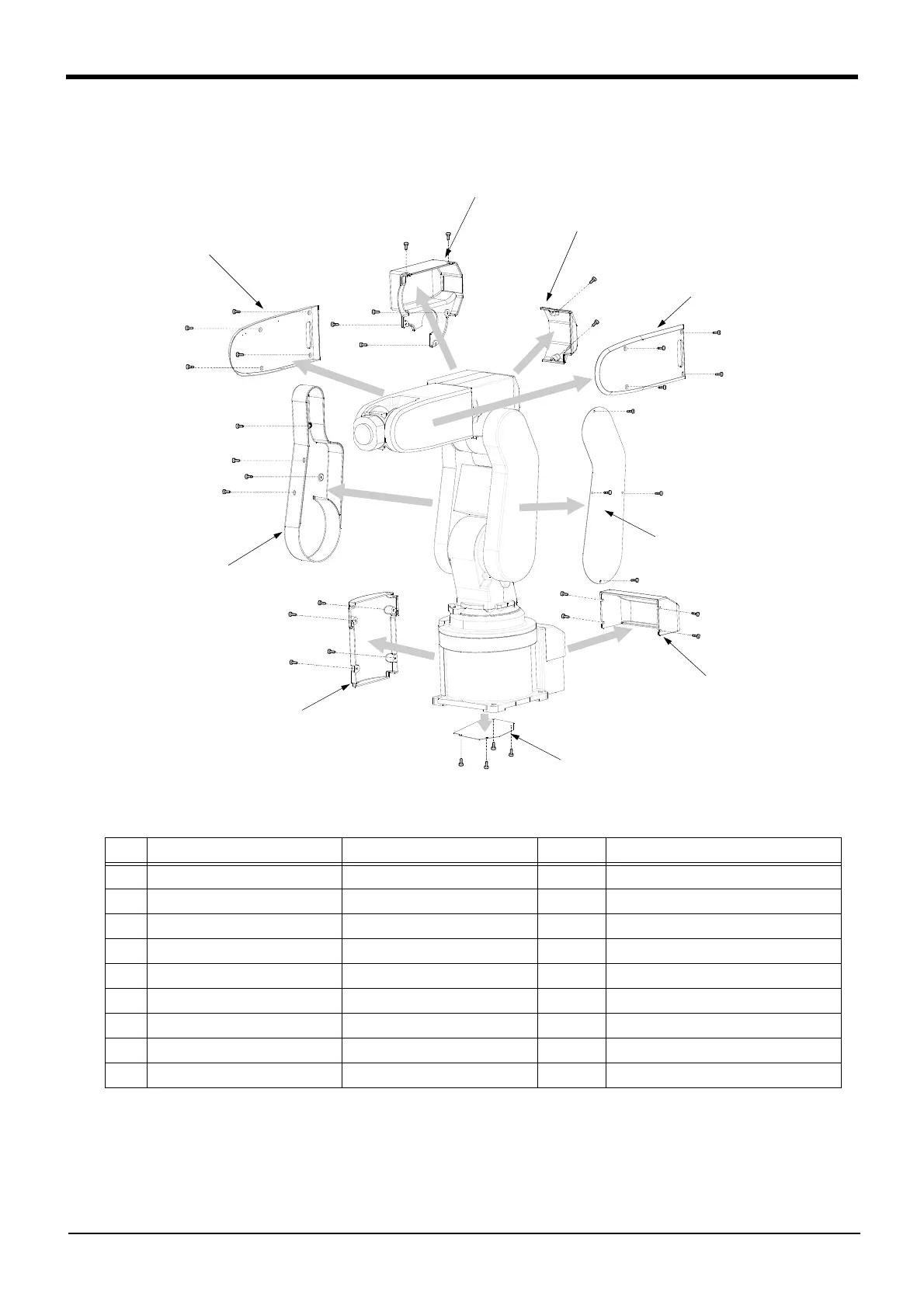
Fig.5-4 : Installing/removing the cover (RV-2FR series)
Table 5-4 : Cover names and installation screw list (RV-2FR series)
(1) Refer to Fig. 5-4 and remove the covers.
(2) The names of the cover and installation screw are given in Table 5-4. The number in Table 5-4 correspond
to Fig. 5-4.
No Cover names
Installation screw
Note1)
Note1)The tightening torque of each screws are shown below.
M3 screw: 0.608 to 0.824Nm
Qty
Remarks
<1> Battery cover Bind screw M3 1
<2> J1 motor cover Bind screw M3 1
<3> No. 1 arm cover R Bind screw M3 1
<4> No. 1 arm cover L Low head safety socket M3 1 Nickel-plated screw.
<5> Elbow cover B Bind screw M3 1
<6> Elbow cover R Bind screw M3 1
<7> No. 2 arm cover L Bind screw M3 1
<8> No. 2 arm cover R Bind screw M3 1
<9> Bottom plate Low head safety socket M3 1 Nickel-plated screw.
<6> Elbow cover R
<5> Elbow cover B
<8> No.2 arm cover R
<7> No.2 arm cover L
<4> No.1 arm cover L
<3> No.1 arm cover R
<2> J1 motor cover
<1> Battery cover
9. Bottom plate
 Loading...


