FX Series Programmable Controlers Applied Instructions 5
5-85
5.7.1 IST (FNC 60)
Operation:
This instruction automatically sets up a multi-mode
STL operating system. This consists of variations
of ‘manual’ and ‘automatic’ operation modes.
Points to note:
a) The IST instruction automatically assigns
and uses many bit flags and word devices;
these are listed in the boxed column on the
right of this page.
b) The IST instruction may only be used
ONCE.
It should be programmed close to the
beginning of the program, before the
controlled STL circuits.
c) The required operation mode is selected by
driving the devices associated with
operands
S+0 through to S+4 (5 inputs). None of the
devices within this range should be ON at
the same time. It is recommended that these
‘inputs’ are selected through use of a rotary
switch.
If the currently selected operating mode is
changed before the ‘zero return complete’
flag (M8043) is set, all outputs will be turned
OFF.
d) The ‘zero position’ is a term used to identify
a datum position from where the controlled
device, starts from and returns too after it
has completed its task. Hence, the operating
mode ‘zero return’, causes the controlled
system to return to this datum.
Mnemonic Function
Operands
Program steps
S
1 S2 S3
IST
FNC 60
(
Initial state)
Automatically sets
up a multi-mode
STL operating
system
X, Y, M, S,
Note:
uses 8
consecutive devices
S,
Note:
FX
0 users S20 to S63
FX0N users S20 to S127
FX users S20 to S899
D1must be lower than D2
IST:
7steps
FX
1S
FX
1N
FX
2N
FX
2NC
PULSE-P
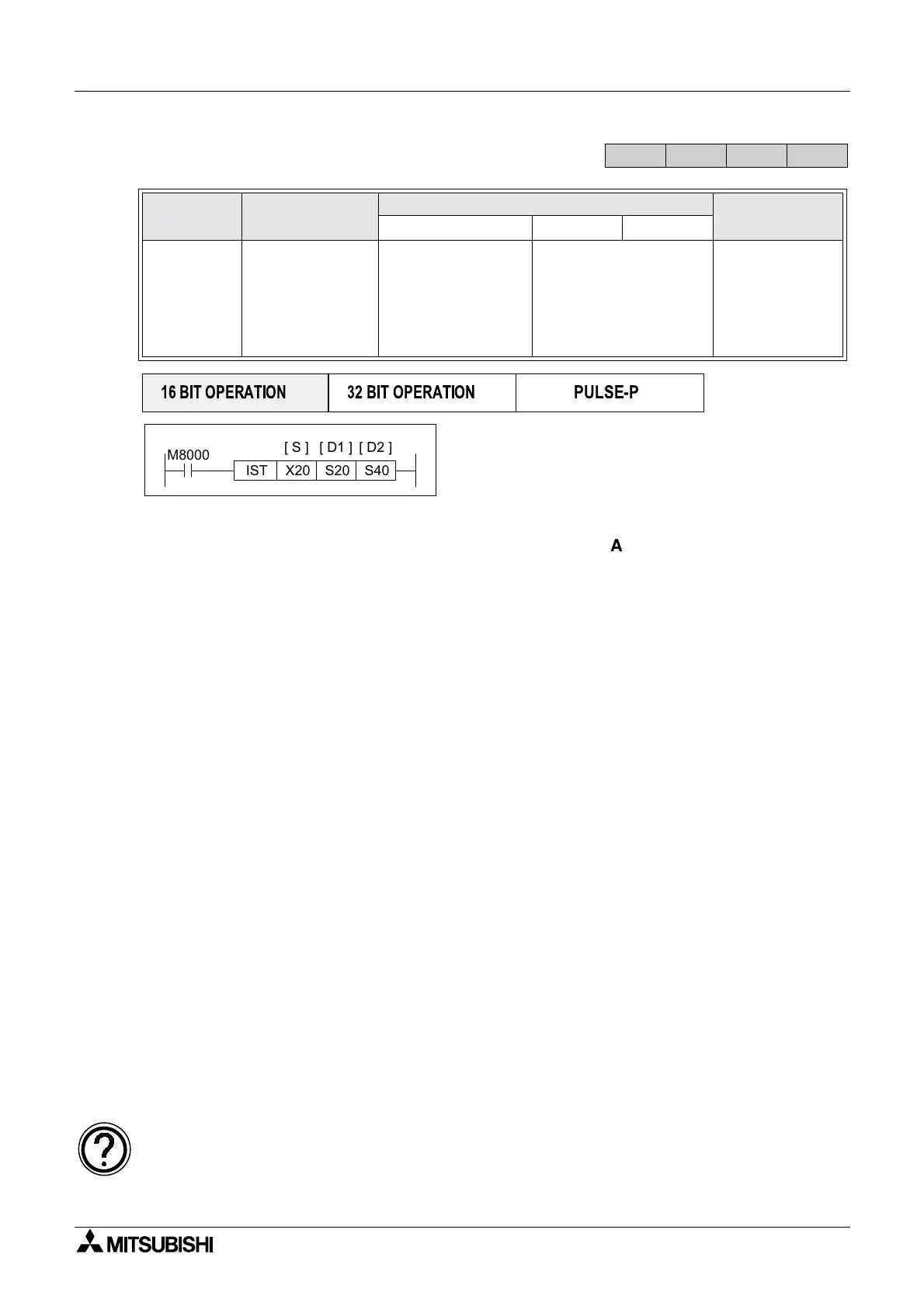
16 BIT OPERATION
32 BIT OPERATION
M8000
S20X20 S40IST
[ S ] [ D1 ] [ D2 ]
Assigned devices
Indirect user selected devices:
S
+0 Manual operation
S
+1 Zero return
S
+2 Step operation
S
+3 One cycle operation
S
+4 Cyclic operation
S
+5 Zero return start
S
+6 Automatic operation start
S
+7 Stop
Initial states:
S0 initiates ‘manual’ operation
S1 initiates ‘zero return’ operation
S2 initiates ‘automatic’ operation
General states:
S10toS19‘zero return’ sequence
D
1 to D2 ‘automatic return’ sequence
Special bit flags:
M8040 = ON STL state transfer is inhibited
M8041 = ON initial states are enabled
M8042 = Start pulse given by start input
M8043 = ON zero return completed
M8044 = ON machine zero detected
M8047 = ON STL monitor enabled
The ‘zero’ position is sometimes also referred to as a home position, safe position, neutral
position or a datum position.
 Loading...


