FX Series Programmable Controlers Applied Instructions 5
5-157
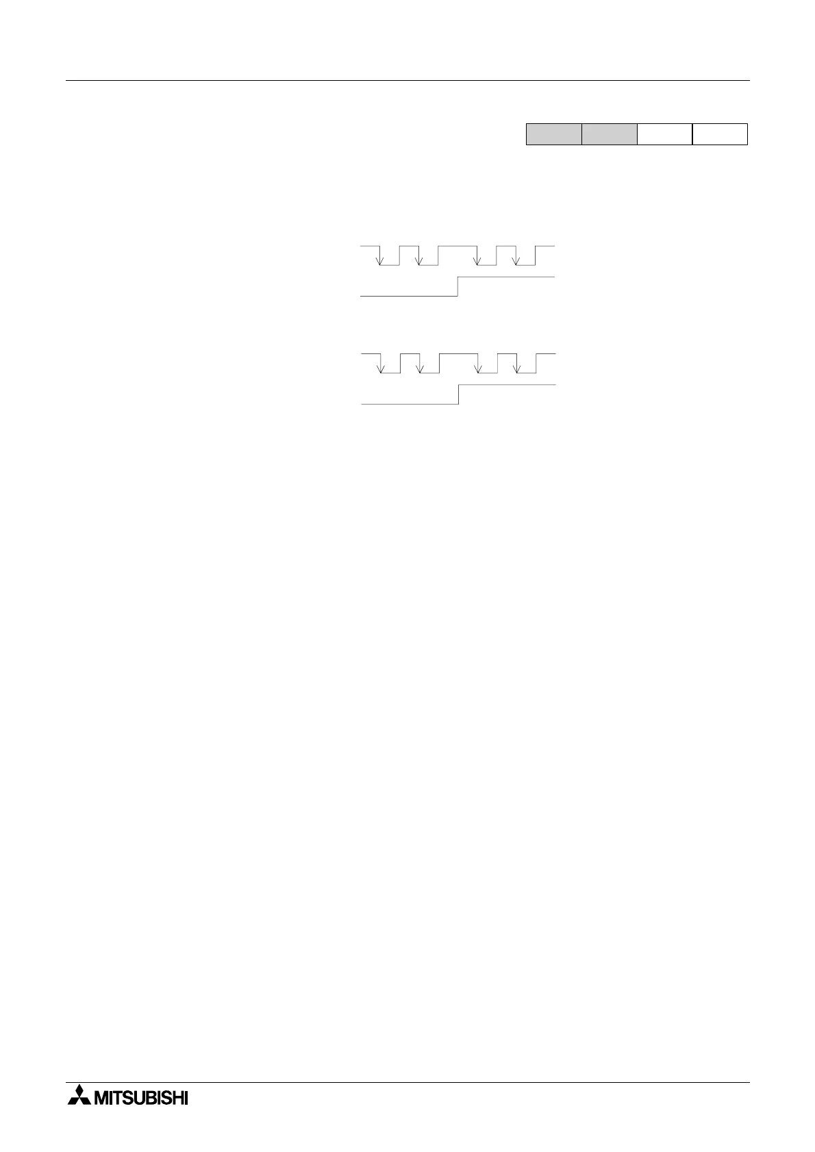
5.13.2 Pulse train settings
When a positioning operation is executed from the PLC, the pulse output signal has the ‘Pulse
train + Sign’ format during control, as shown in the figure below.
Make sure to set the pulse train input mode on the servo amplifier or stepper motor as follows;
Pulse train input mode: Pulse train + Sign
Pulse train logic: negative logic
FX1S
FX
1N
FX
2N
FX
2NC
Pulse output from Y000
Arbitrary output relay
Y
¨¨¨
(Specifies the direction.)
ON OFF
Pulse output from Y001
Arbitrary output relay
Y
¨¨¨
(Specifies the direction.)
ON OFF

 Loading...


