FX Series Programmable Controllers Points Of Technique 10
10-31
10.19.4 Specified device monitor
It is possible to specify in the PLC, the devices to be displayed on the 5DM.
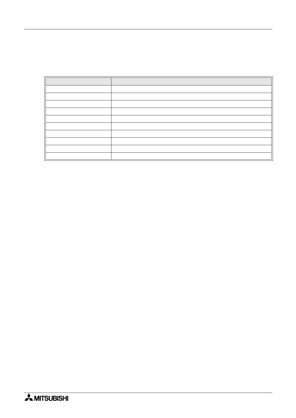
When specifying a device to be displayed, write the correcponding number shown in the table
below to D1.
*1 If a numeric value other than 1~9 is writen, no device will be specified. In this case all
operator functions are valid.
Points to note:
a)During the monitoring of devices T or C, if a device number not used in the program is
specified, the next largest existing device number is displayed. If the specified device
number is beyond the range available, the largest existing device number will be displayed.
If the OUT instruction for the T or C is not present in the sequence program, ‘----’ is displayed
on the 5DM screen.
b)When scrolling and displaying consecutive devices using the operation keys, move up and
down the range with the [+] and [-] keys.
c)If the device numbers are not consecutive, and scrolling is required, some additional PLC
code will be needed. The range of device numbers to be displayed will have to be related to
an index register, the [+] and [-] keys increment and decrement the current value of this
register, and therefore change the displayed values.
d)If data registers used in D8158 are located in the non-backup area, the current values of the
data registers are reset to ‘0’ when the PLC is stopped. As a result of this, the device type to
be displayed, set by
D1 becomes invalid and, the operator functions become valid.
In order to disable the operator functions, use data registers located in a battery backed
area.
Current value of D1
Device type
1 Input (X)
2Output(Y)
3 Auxiliary relay (M)
4State(S)
5Timer(T)
6 Counter (C), 16-bit current and set value or 32-bit set value
7 Data register (D) 16-bit
8 Data register (D) 32-bit
9Timedisplay
Any other value Not used *1

 Loading...


