FX Series Programmable Controlers Applied Instructions 5
5-118
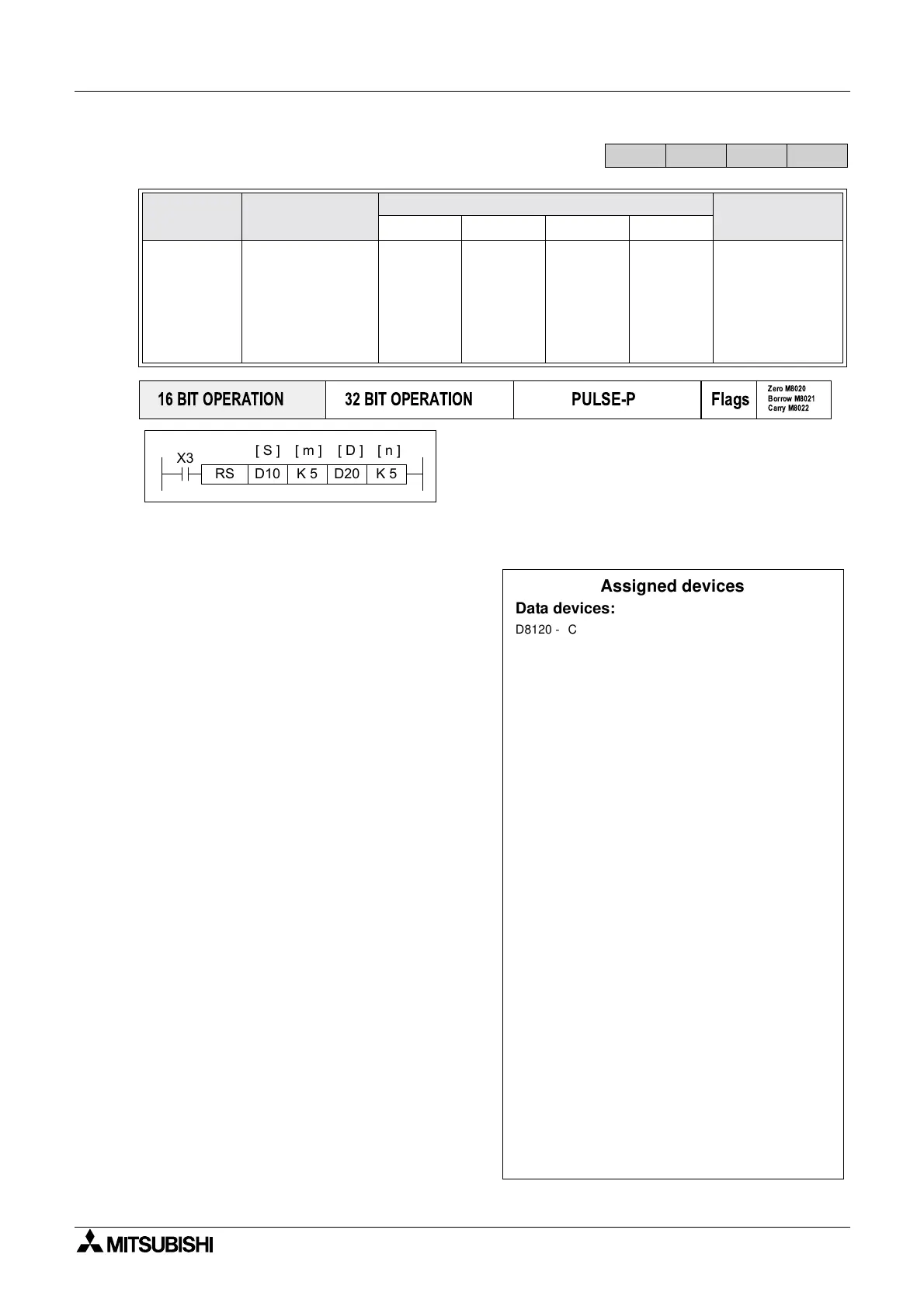
5.9.1 RS (FNC 80)
Operation:
This instruction performs the direct control of
communications over FX and FX
0N communication
adapters which connect to the left hand port of the
Main Processing Unit, i.e. FX
0N-232ADP, FX-
232ADP etc.
Points to note:
a) This instruction has many automatically
defined devices. These are listed in the
boxed column to the right of this page.
b) The RS instruction has two parts, send
(or transmission) and receive. The first
elements of the RS instruction specify the
transmission data buffer (S) as a head
address, which contains m number of
elements in a sequential stack.
The specification of the receive data area
is contained in the last two parameters of
the RS instruction. The destination (D)
for received messages has a buffer or
stack length of n data elements. The size
of the send and receive buffers dictates
how large a single message can be.
Buffer sizes may be updated at the
following times:
1) Transmit buffer - before transmission
occurs, i.e. before M8122 is set ON
2) Receive buffer - after a message has
been received and before M8123 is
reset.
c) Data cannot be sent while a message is
being received, the transmission will be
delayed - see M8121.
d) More than one RS instruction can be
programmed but only one may be active
at any one time.
e) Refer to the FX Communications Manual
when using this function
Mnemonic Function
Operands
Program steps
SmDn
RS
FNC 80
(Serial Com-
munications
instruction)
Used to control
serial
communications
from/to the
programmable
controller
D
(including
file
registers)
K, H,
D
)
m=1to
256, FX2N
1 to 4096.
DK,H,
D
)
m=1to
256, FX2N
1to4096
RS: 9 steps
FX
1S
FX
1N
FX
2N
FX
2NC
PULSE-P
16 BIT OPERATION
32 BIT OPERATION
Flags
Zero M8020
Borrow M8021
Carry M8022
X3
K 5
[ S ] [ D ]
D20RS K 5D10
[ m ] [ n ]
Assigned devices
Data devices:
D8120 - Contains the configuration parameters for
communication, i.e. Baud rate,Stop bits etc. Full
details over the page
D8122 - Contains the current count of the number of
remaining bytes to be sent in the currently
transmitting message.
D8123 - Contains the current count of the number of
received bytes in the ‘incoming’ message.
D8124 - Contains the ASCII code of the character used
to signify a message header - default is ‘STX’,
02 HEX.
D8125 - Contains the ASCII code of the character used
to signify a message terminator -default is
‘ETX’,03HEX.
Operational flags:
M8121 - This flag is ON to indicate a transmission is
being delayed until the current receive
operation is completed.
M8122 - This flag is used to trigger the transmission of
data when it is set ON.
M8123 - This flag is used to identify (when ON) that a
complete message has been received.
M8124 - Carrier detect flag. This flag is for use with FX
and FX2C Main Processing Units. It is typically
useful in modem communications
M8161 - 8 or 16 bit operation mode ON = 8 bit mode
where only the lower 8 bits in each source or
destination device are used, i.e. only one ASCII
character is stored in one data register OFF =
16bit mode where all of the available source/
destination register is used, i.e. two ASCII
characters are stored in each data register.

 Loading...


