FX Series Programmable Controlers Applied Instructions 5
5-107
5.8.5 SEGL (FNC 74)
Operation:
This instruction takes a source decimal value (S)
and writes it to a set of 4 multiplexed, outputs (D).
Because the logic used with latched seven
segment displays varies between display manufactures, this instruction can be modified to suit
most logic requirements. Configurations are selected depending on the value of n, see the
following page.
Points to note:
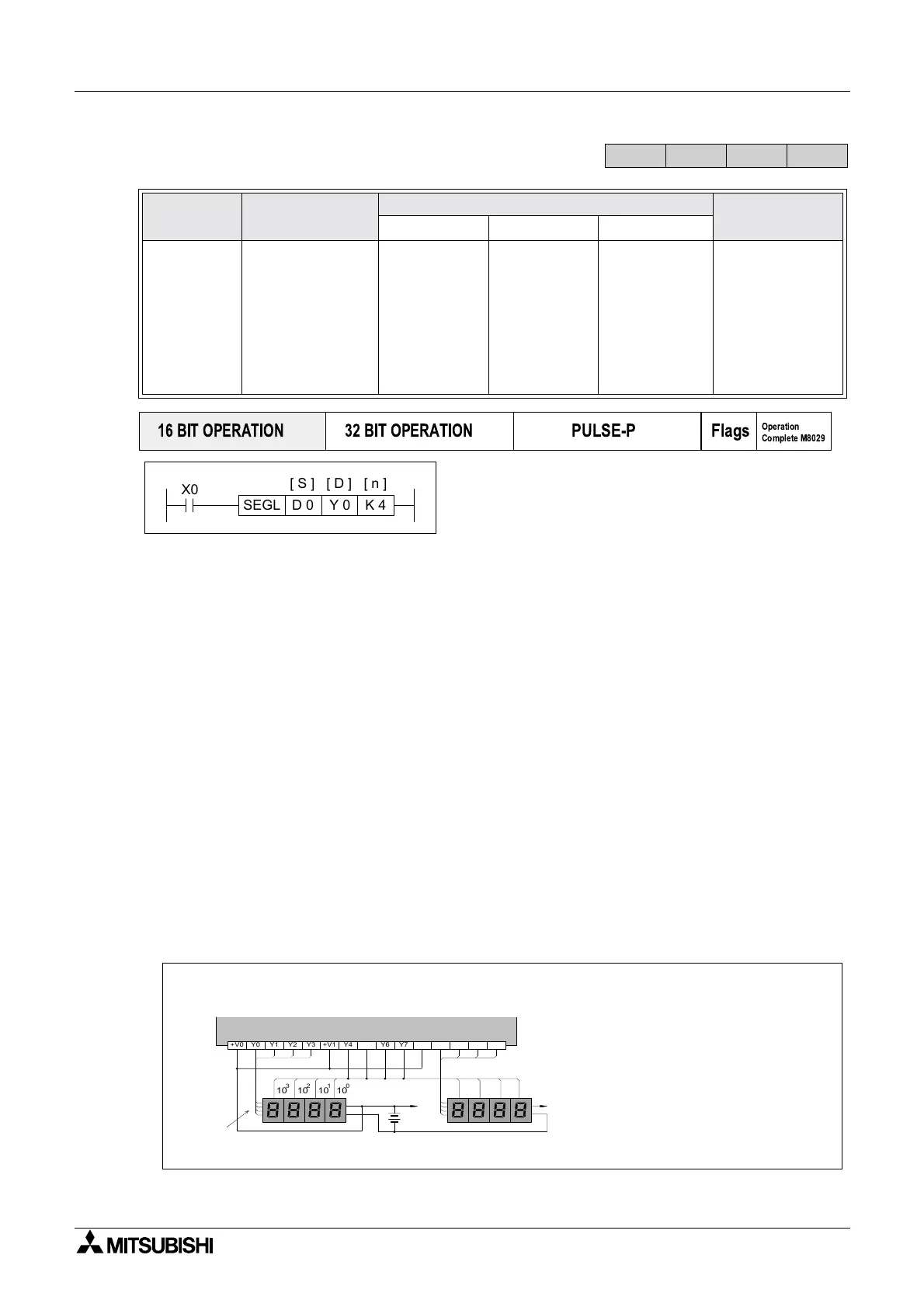
a) Data is written to a set of multiplexed outputs (D
+0 to D+7, 8 outputs) and hence seven
segment displays. A set of displays consists of 4 single digit seven segment units. A
maximum of two sets of displays can be driven with this instruction. When two sets are used
the displays share the same strobe outputs (D
+4 to D+7 are the strobe outputs). An
additional set of 4 output devices is required to supply the new data for the second set of
displays (D
+10 to D+13, this is an octal addition). The strobe outputs cause the written data to
be latched at the seven segment display.
b) Source data within the range of 0 to 9,999 (decimal) is written to the multiplexed outputs.
When one set of displays are used this data is taken from the device specified as operand
S. When two sets of displays are active the source device S
+1 supplies the data for the
second set of displays. This data must again be within the range 0 to 9,999. When using
two sets of displays the data is treated as two separate numbers and is not combined to
provide a single output of 0 to 99,999,999.
c) The SEGL instruction takes 12 program scans to complete one output cycle regardless of
the number of display sets used. On completion, the execution complete flag M8029 is set.
Mnemonic Function
Operands
Program steps
SD n
SEGL
FNC 74
(
Seven
segment
with latch)
Writes data to
multiplexed single
digit displays - 4
digits per set,
max. 2 sets
K, H
KnX, KnY,
KnM, KnS
T, C, D, V, Z
Y
Note:
n=0to3,8
outputs are
used
n=4to7,12
outputs are
used
K, H,
)
Note:
n=0to3,1set
of 7 Seg active
n=4to7,2sets
of 7 Seg active
SEGL:
7steps
FX
1S
FX
1N
FX
2N
FX
2NC
PULSE-P
16 BIT OPERATION
32 BIT OPERATION
Flags
Operation
Complete M8029
X0
D 0 Y 0 K 4SEGL
[ D ][ S ] [ n ]
10101010
3012
Y2 Y3+V0 Y0 Y1 Y6 Y7+V1 Y4 Y5 Y12 Y13+V2 Y10 Y11
1248
10
10
1010
30
1
2
V+
V+
1
2
4
8
1
2
4
8
1248
Transistor Output (Source)
BCD
data
signals
Display set 2
Display set 1
In this example it has
been assumed that the
seven segment displays
accept data HIGH inputs
and latch when a HIGH
signal is received
Note: A single set of strobe signals are always used
regardless of the number of display sets.

 Loading...


