FX Series Programmable Controllers Points Of Technique 10
10-2
10.3 Using The Forced RUN/STOP Flags
10.3.1 A RUN/STOP push button configuration
The FX programmable controller has a single RUN terminal. When power is applied to this
terminal the PLC changes into a RUN state, i.e. the program contained is executed.
Consequently when there is no power 'on' the RUN terminal the PLC is in a STOP state.
This feature can be utilized to provide the FX PLC with an external RUN/STOP - push button
control. The following PLC wiring and program addition are required.
Explanation:
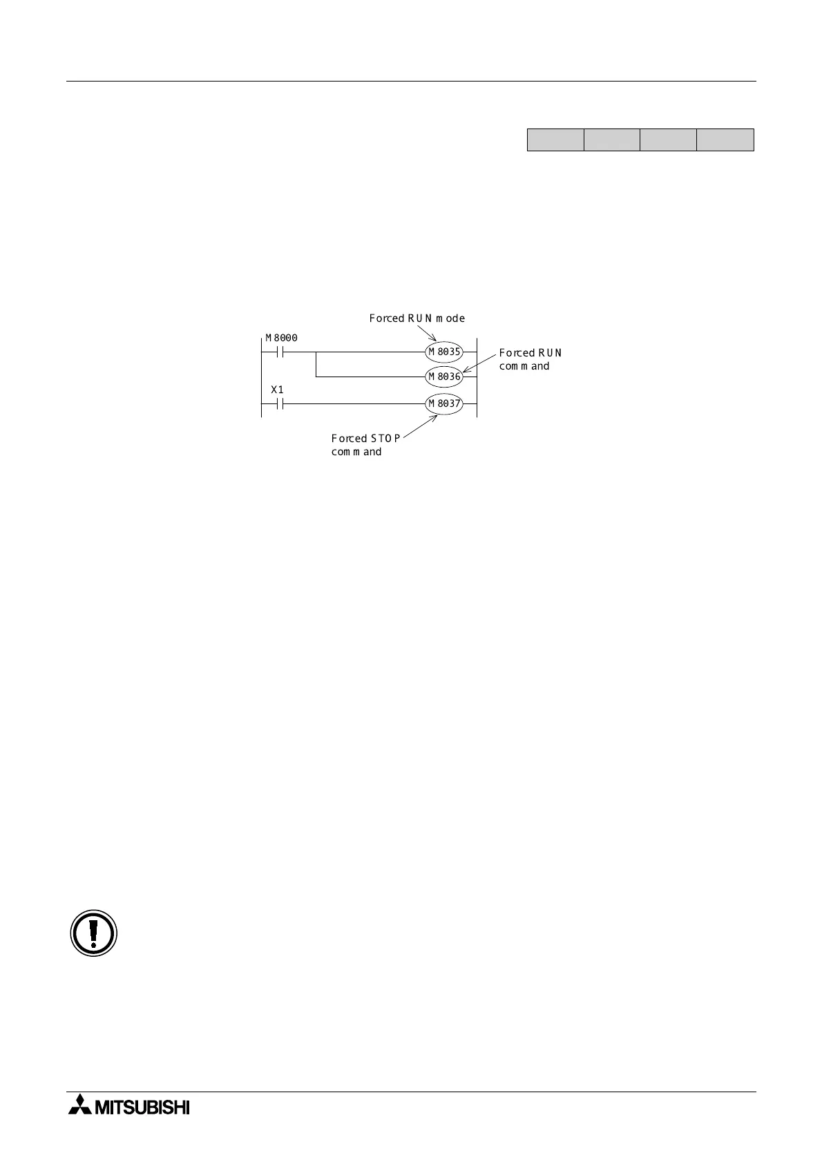
Pressing the RUN push button sets the PLC into the RUN state. This means M8000 is ON.
Following the program, M8000 activates both M8035 and M8036. These two special auxiliary
devices set the PLC in to forced RUN mode. Releasing the RUN push button would normally
return the PLC to the STOP state, but because the two auxiliary coils, M8035 and 36 are ON,
the PLC remains in RUN. To stop the, PLC pressing the STOP push button drives an input ON
and consequently M8037 turns ON. This then automatically forces OFF both M8035 and 36
and resets itself. Hence, the PLC is in its STOP status and awaits the cycle to begin again.
Input priority:
• The STOP input is only processed after the programs END statement has been reached -
this is because the physical input used, i.e. an X device is normally updated and processed
at that time. Therefor, the RUN input is given priority when both RUN and STOP inputs are
given simultaneously.
• To give priority to the STOP input and provide a 'safer' system, some form of mechanical/
circuitry interlock should be constructed between both RUN and STOP inputs. A very
simple example is shown in the wiring diagram above.
• For push-button control to operate correctly, the user must set the RUN/STOP switch on
FX
2N and FX2NC units to the STOP position.
• FX
2N and FX2NC units do not have a RUN terminal. One of the inputs X0 to X17 (X0 to X7
for FX
2N-16M) on the MPU should be configured as a RUN terminal in the parameter
settings.
FX
1S
FX
1N
FX
2N
FX
2NC
M 8000
M8035
X1
M8036
M8037
Forced S TO P
command
Forced R U N
c om m and
ForcedRUN mode

 Loading...


