FX Series Programmable Controlers Applied Instructions 5
5-191
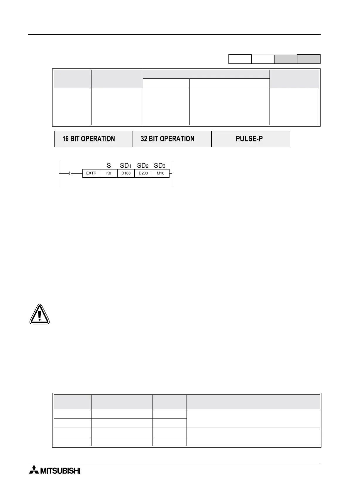
5.16.1 EXTR (FNC 180)
Operation:
The value of S stored in the extension ROM (K0 to
K32767) defines the function number and the
instruction.
SD
1,SD2 and SD3 are parameters of the
application instruction. S or D varies depending on
the function number. The type of operation (16 bit,
32 bit, pulse) is determined from the instruction
number.
Points to Note:
In some function numbers, the parameters SD
1 to SD3 may not be required due to
specifications. In such a case K0 should be written in the program. K0 is ignored in the internal
processing of the PLC.
As each of the external ROM cassettes (FX
2N-ROM-E1 and FX2NC-ROM-CE1) attach to the
memory port of an FX
2N or FX2NC series PLC, both are equipped with a 16K step EEPROM. In
addition, the FX
2NC-ROM-CE1 also contains a real-time clock.
Accordingly, the FX
2N-ROM-E1 and FX2NC-ROM-CE1 are compatible as advanced units of the
FX-EEPROM-16 and FX
2NC-EEPROM16C respectively.
The FX
2N-ROM-E1 and FX2NC-ROM-CE1 are only operable with FX2N and FX2NC units of
V3.00 or later
5.16.1.1 Inverter Communication
External ROM cassette functions 10 to 13 are for reading and writing data to/from an inverter
using signal instructions. These functions are available when an FX
2N-485-BD or FX0N-
485ADP is attached to the PLC, for communication with a Mitsubishi Electric A500/E500/S500
series inverter.
Mnemonic Function
Operands
Program steps
SSD
1 SD2 SD3
EXTR
FNC 180
(External
ROM)
External ROM
instruction,
execution
commands
K, H, K, H, KnX, KnY, KnM, KnS,
T, C, D, V, Z,
X, Y, M, S.
EXTR
9 steps
DEXTR,
DEXTRP
17 steps
Function
No.
Function
Data
Direction
Reference to Inverter manual
EXTR K10 Operation monitoring INV to PLC Execute operation control as for computer link, and
refer to ‘monitoring’ for communication functions.
EXTR K11 Operation Control PLC to INV
EXTR K12 Parameter read INV to PLC Refer to the parameter code list in the relevant
manuals appendix.
EXTR K13 Parameter write PLC to INV
FX
1S
FX
1N
FX
2N
FX
2NC
PULSE-P
16 BIT OPERATION
32 BIT OPERATION
EXTR K0 D100 D200 M10
SSD1 SD2 SD3

 Loading...


