FX Series Programmable Controlers Applied Instructions 5
5-126
5.9.8 PID (FNC 88)
Operation:
This instruction takes a current value (S
2) and
compares it to a predefined set value (S
1). The
difference or error between the two values is then
processed through a PID loop to produce a
correction factor which also takes into account previous iterations and trends of the calculated
error. The PID process calculates a correction factor which is applied to the current output
value and stored as a corrected output value in destination device (D). The setup parameters
for the PID control loop are stored in 25 consecutive data registers S
3+0 through S3+24.
Points to note:
a) Every PID application is different. There will be a certain amount of “trial and error”
necessary to set the variables at optimal levels.
b) On FX
2N, FX2NC &FX1N MPUs a Pre-tuning feature is available that can quickly provide
initial values for the PID process. Refer to page 10-28 for more details.
c) The FX
1S does not have analog capabilities, it is therefore necessary to use RS232
communications to achieve basic PID operation.
d) As 25 data register are required for the setup parameters for the PID loop, the head address
of this data stack cannot be greater than D975. The contents of this data stack are
explained later in this section. Multiple PID instructions can be programmed, however each
PID loop must not have conflicting data registers.
e) There are control limits in the PLC intended to help the PID controlled machines operate in
a safe manner. If it becomes necessary to reset the Set Point Value (S
1
) during operation, it
is recommended to turn the PID command Off and restore the command after entering the
new Set Point Value. This will prevent the safety control limits from stopping the operation of
the PID instruction prematurely.
f) The PID instruction has a special set of error codes associated with it. Errors are identified in
the normal manner. The error codes associated with the PID loop will be flagged by M8067
with the appropriate error code being stored in D8067. These error devices are not
exclusive to the PID instruction so care should be taken to investigate errors properly.
Please see chapter 6, ‘Diagnostic Devices’ for more information.
g) A full PID iteration does not have to be performed. By manipulation of the setup parameters
P (proportional), I (Integral) or D (derivative) loops may be accessed individually or in a user
defined/selected group. This is detailed later in this section.
Mnemonic Function
Operands
Program steps
S
1 S2 S3 D
PID
FNC 88
(PID
control loop)
register each
Receives a data
input and
calculates a
corrective action
to a specified
level based on
PID control
D
)
Note: S1 and S2
use a single
data register
D
)
Note: S3
uses 25
consecutive
data registers
D
)
Note: D
uses a single
data register
PID:
9steps
FX
1S
FX
1N
FX
2N
FX
2NC
PULSE-P
16 BIT OPERATION
32 BIT OPERATION
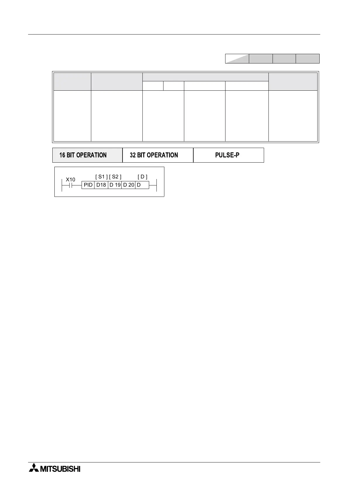
X10
D 19D18PID
[ S1 ] [ S2 ] [ D ]
D 20 D 46
[ S3 ]

 Loading...


