5-46 Troubleshooting Charts: FGU Failure
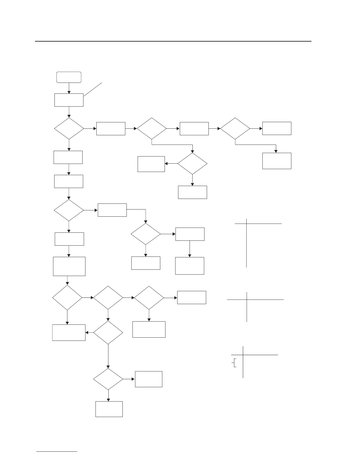
5.19 FGU Failure
VCO TX/RX
unlock
“Sniff ”
Frequency near
VCO shield
Sniff: Using an inductive field probe
as an antenna to measure
frequency. Place the probe
approximately ½ inch away from
components to be sniffed
Frequency
detected?
4.6V at
TP853?
No
Remove
VCO shield.
No
Remove
TRIDENT shield.
5V at
C742?
No
Check
5V DC supply.
Remove
VCO shield.
Check control
Voltage at R764.
<
1Vdc
>10Vdc
or drifting?
Check if VCO
Is locked using
spectrum analyzer.
VCO
Locked?
Yes
No
Check
VOCON board.
Yes
Check parts
around VCOs and
loop filter. If OK,
replace VCO.
Check parts
around U702.
If OK, replace
U702.
Yes
2.5V at
logic pins
on U703?
Yes
Yes
Replace VCO.
Check parts
around U703.
If OK, replace
U703.
Yes
7/800 TX6
700 TX / 800 RX
9
700 RX / 800 TX10
VHF TX8
UHF1 TX (445-470) / UHF2 TX (450-520)13
UHF1 TX (380-445)
12
UHF1 RX (450-470)15
UHF1 RX (380-450) / UHF2 RX (450-520)8
VHF RX4
Freq BandPin
7/800 TX / VHF RXY707
700 RX/TX 800 RX/TXY705
VHF TX / UHF1 RX / UHF2 RXY704
UHF1 TX / UHF2 TXY705
VCORef Des
Y706
No
No
Check power
on prescalar buffer
output ,C779 using
field probe.
Is power at
C779
>-15dBm?
Yes
No
Check parts around
Q774. If OK,
replace Q774.
1.5Vdc at
L701?
Yes
Check
1.5V DC supply.
Check parts
around U702.
If OK, replace
U702.
Is power at
U709 output
>-15dBm?
Yes
No
Is power at
VCO output
>-15dBm?
No
Note 1:
See Note 1
2.5V at
logic pins
on U709?
See Note 3
Yes
7
6
3
Freq BandPin
VHF TX/ UHF1 RX / UHF2 RX
VHF RX / 7/800 TX
700 RX/TX / 800 RX/TX /UHF1 TX/UHF2 TX
Freq BandPin
Note 3:
Check parts
around U703.
If OK, replace
U703.
Yes
Replace U709.
Note 2:
See Note 2
See Note 2
Remove
TRIDENT shield.
U709
No
No
Remove
TRIDENT shield.

 Loading...


