3-26 Theory of Operation: Controller
3.2.1.2.4 Data-Side Microphone
The data-side microphone is mounted on the front chassis and connects directly to the VOCON
board through a set of pogo pins mounted on the VOCON board.
3.2.1.2.5 Side Controls Flex
The side controls flex contains the PTT, Side Top button, Side Middle button and Side Bottom button.
The flex connects to the Expansion Board through a 10-pin connector.
3.2.1.2.6 Audio-Side Microphone, Speaker, and Bluetooth Antenna
The audio-side microphone and speaker flex assembly connects to the expansion board through
spring clips. The Bluetooth antenna is also part of this flex assembly and also connects to the
expansion board through spring clips.
3.2.1.2.7 RF Board
The RF board connects to the VOCON through a 40-pin board to board connector.
NOTE: See Table 7-2 on page 7-2 for pin assignments
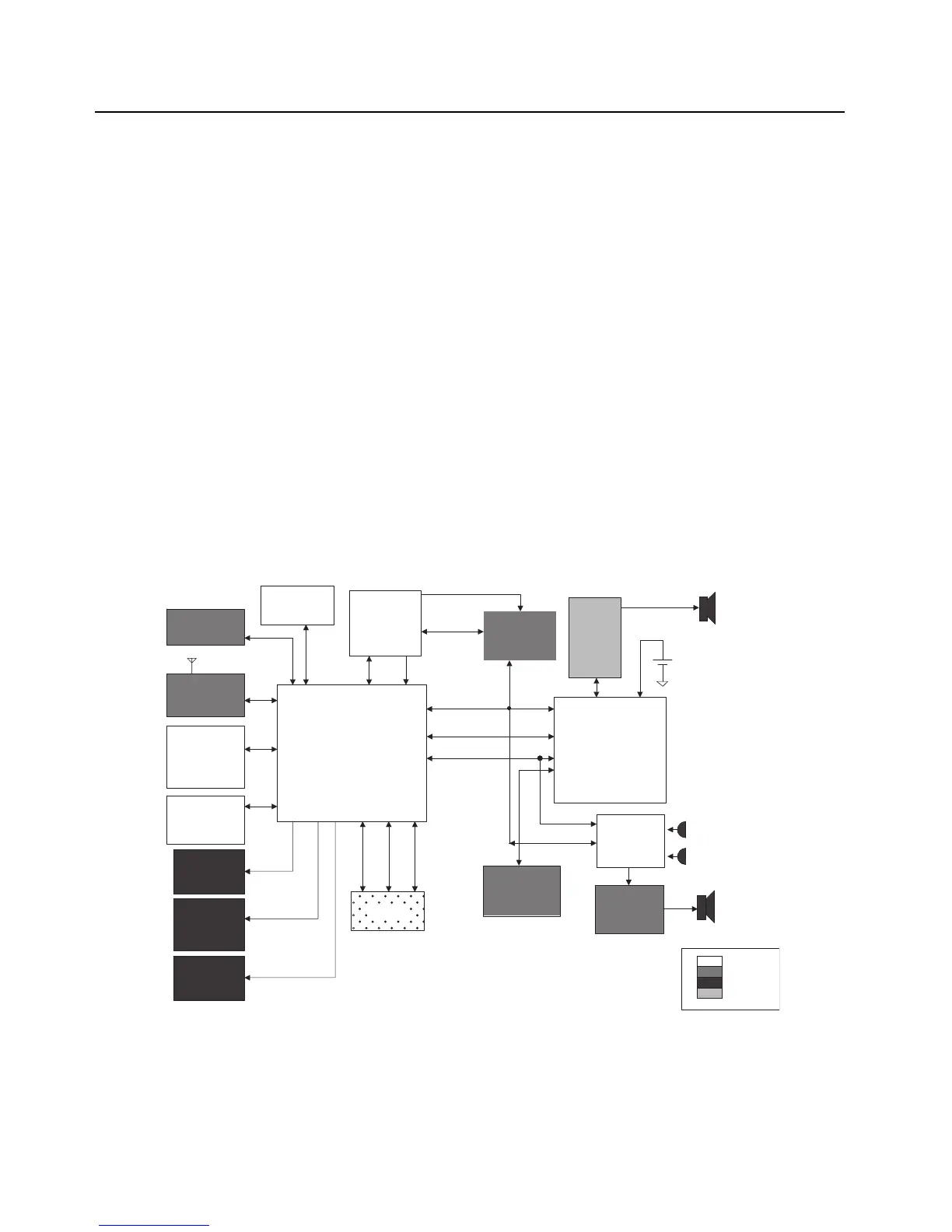
3.2.1.3 Controller Electrical Architecture
An overview of the Controller electrical architecture is shown in Figure 3-15 below. The major
components and electrical interfaces are shown.
Figure 3-15. Controller Electrical Overview
OMAP 1710
Processor
FLASH
64 MB
Front
Display
Side
Conn -
GCAI
GPS/ BT Chipset
(TINL5500)
CPLD
SDRAM
32 MB
Audio SSI 1
Class D
Audio PA
MACE
Secure
IC
MAKO IC
e-MMC
Flash Memory
Top Display
Main
Speaker
Dual
Microphones
Radio
Battery
+
-
4.096 MHz Clk
Lighting
Controller
USB / UART
SPI
Keypad /
Switches
I2C
SPI
SoSSI
Keypad
SSI
32 kHz ClkEMIFS
SDIO 2
UART 2
EMIFS
EMIFF
SPI GPIOSSI
Accessory
Audio
Codec
VOCON
Expansion
Module
GCAI
SPI
RF Board
GPS/BT Module
(TINL5500 &
ATMEL AVR32)

 Loading...


