3-24 Theory of Operation: Controller
3.2 Controller
3.2.1 Controller Overview
This section provides a detailed circuit description of the APX 5000/APX 6000/APX 6000XE/
SRX 2000 controller design. The controller design consists of the following board and flexes:
Printed Circuit Boards
• VOCON Board
• Expansion Board
• GCAI Connector Board
Flexes
• Control Top (Top Display, Buttons, Knobs)
• Front Chassis Display
• Front Chassis Keypad
• GCAI (Global Core Accessory Interface)
• Side Controls
• Audio Side Microphone / Speaker / Bluetooth Antenna
• Data Side Microphone
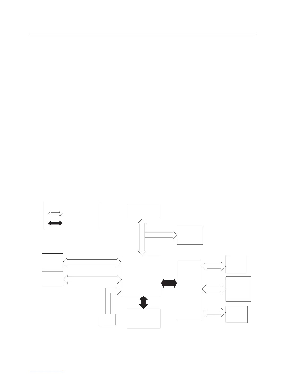
The controller interconnection diagram (Figure 3-14) shows the various physical components of the
design, along with how they are all connected. It also shows the key distinguishes between a flex
connection and a board-to-board connection. A brief description of each of the components is
provided below.
Figure 3-14. Controller Interconnection Diagram
VOCON
Board
Expansion
Board
Audioside
Speaker
& Mic;
BT Antenna
Top Display
Side
Controls
Top
Controls
Front
Display
GCAI
Data
Mic
RF Board
= Board to Board
= Flex
KEY
Keypad

 Loading...


