Theory of Operation: Bluetooth 3-71
3.5.3 Bluetooth I/Os.
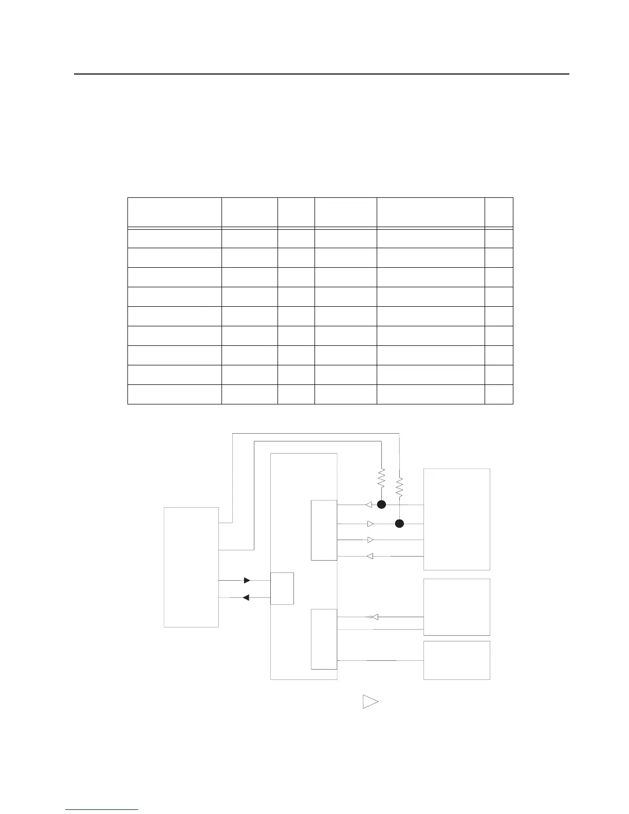
The communication between the Bluetooth IC and the host controller is by a four-wire HCI USART0
bus (RX, TX, CTS, RTS). The Bluetooth IC receives a firmware update over USART0 each time it is
powered on. The LF receiver IC transmits its data over the USART1 s used for displaying debugging
messages.
Figure 3-55. Bluetooth LF UART Connection Block Diagram
Table 3-16. Bluetooth Host Processor UART I/O
Signal Name Pad Name GPIO MUX
Function
Expansion Board
Schematic Name
I/O
USART0 – RXD PA00 0 A BT_UART_TX_3.3V I
USART0 – TXD PA01 1 A BT_UART_RX_3.3V O
USART0 – RTS PA03 3 A BT_UART_CTS_3.3V O
USART0 – CTS PA04 4 A BT_UART_RTS_3.3V I
USART1 – RXD PA05 5 A USART1_RX I
USART1 – TXD PA06 6 A USART1_TX O
USART1 – CLK PA07 7 A USART1_CLK I
USART2 – RXD PB29 61 A AVR_USART2_RX I
USART2 – TXD PB30 62 A AVR_USART2_TX O
JTAG Connector
ATMEL AVR32
AT32UC3A0512
TI NL 5500
Bluetooth/GPS
Low Frequency
Receiver AS3930
LF Transmit
(OR Gate)
Pin 19
Pin 20
Pin 12
Pin 13
PB29
PB30
PA00
PA01
PA03
PA04
PA05
PA07
PA06
J6
H6
J7
J8
K11
J10
L12
A4
B5
B4
B7
9
10
HCI_TX
HCI_RX
HCI_CTS
HCI_RTS
DAT
CL_DAT
Debug RX
Debug TX
K6
K7
USART2
USART0
USART1
= Level Translator. 3.3volts on AVR side

 Loading...


