5-48 Troubleshooting Charts: GPS Failure
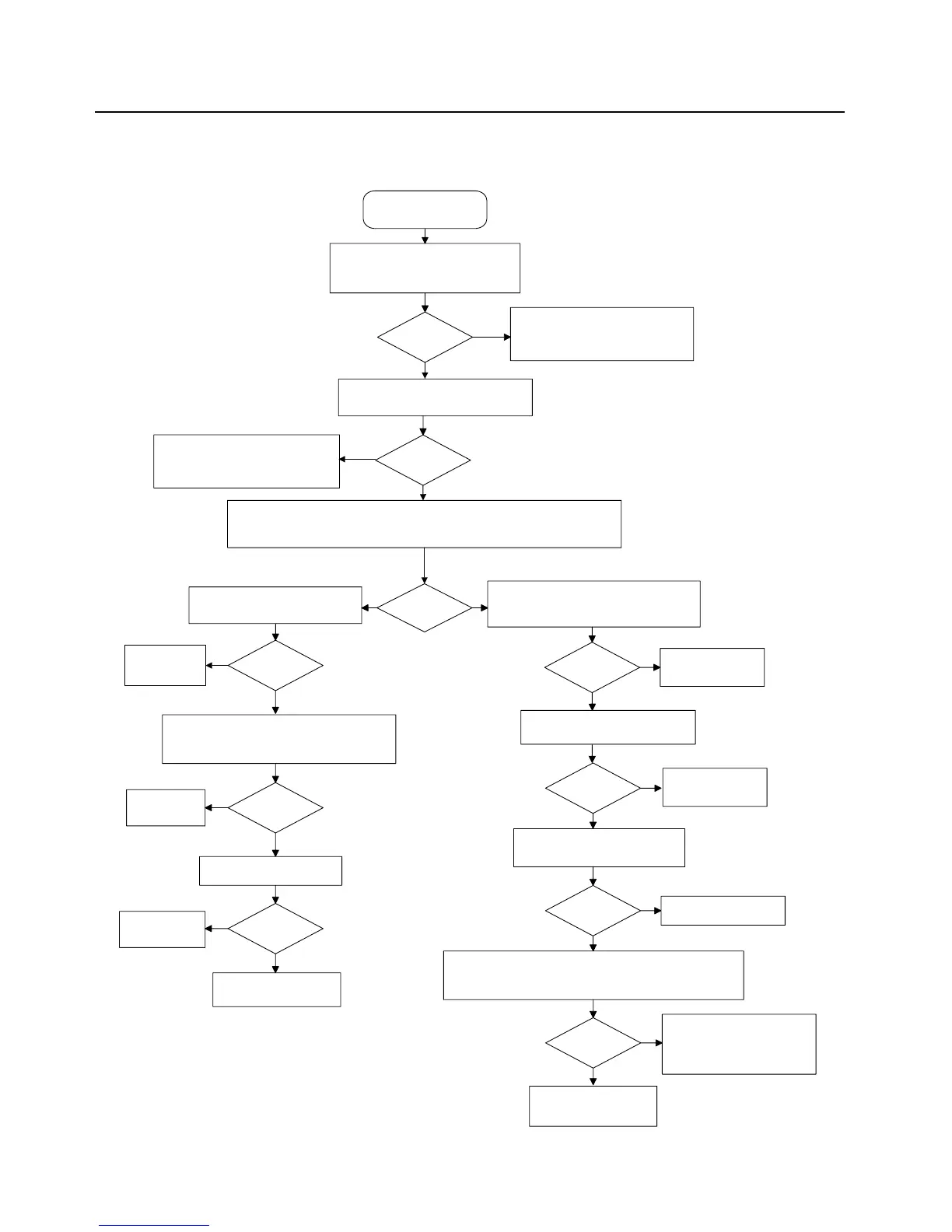
5.21 GPS Failure
START
No GPS Lock
GPS lock?
Verify the location feature is enabled,
replace antenna, and retry in a strong
signal environment (open sky)
Check for 32 kHz clock at TP2405, and
1.8V for GPS reset at TP2406
No
Yes
The GPS receiver requires a working
antenna, and a direct view of the sky
in order to achieve a position fix
32 kHz and
reset ok?
Check U6101 (CPLD) pin E2 (IO74)
for 32 kHz output, and pin D12 (IO91)
for 1.8V on reset.
Re-flash radio with latest released
firmware
GPS lock?
Regulators
OK?
Radio firmware
was corrupted
Replace faulty
regulator
Replace GPS IC U2401
Check for 26 MHz at C2421
Remove expansion board shield and check
VBAT voltage for 3.5V (measured at R2413),
and VDDS for 1.8V (measured at R2415)
No
No
Yes
Yes
Yes
Is 26 MHz
present?
Replace Y2204
No
No
Verify communication with GPS IC by resetting radio while probing TP2047 and
TP2048 with an oscilloscope. Activity should be seen on both UART test points
for successful comm.
No
comm
succesful?
Yes
Yes
Check for 1.8V on LNA enable
measured at TP2402 and C2409
1.8V?
Yes
Replace GPS IC U2401
Remove expansion board shield and
check regulator U2405 for 2.8V (measured
at C2403)
Regulator
OK?
Regulator
OK?
Replace faulty
regulator
Replace faulty
regulator
No
Yes
Yes
No
Measure the GPS total front-end gain @ 1575.42 MHz while
GPS IC is active (measured from antenna port to C2424).
Total gain should be approximately 18 dB.
~ 18 dB?
No
Yes
Debug front-end for faulty
component (LNA’s U1304,
U2404, and SAW filters
FL1301, FL2401 and FL2403)
Replace GPS IC U2401
No
Check regulator U201 for 3V
on RF board (measured at C1305)

 Loading...


