Theory of Operation: Bluetooth 3-73
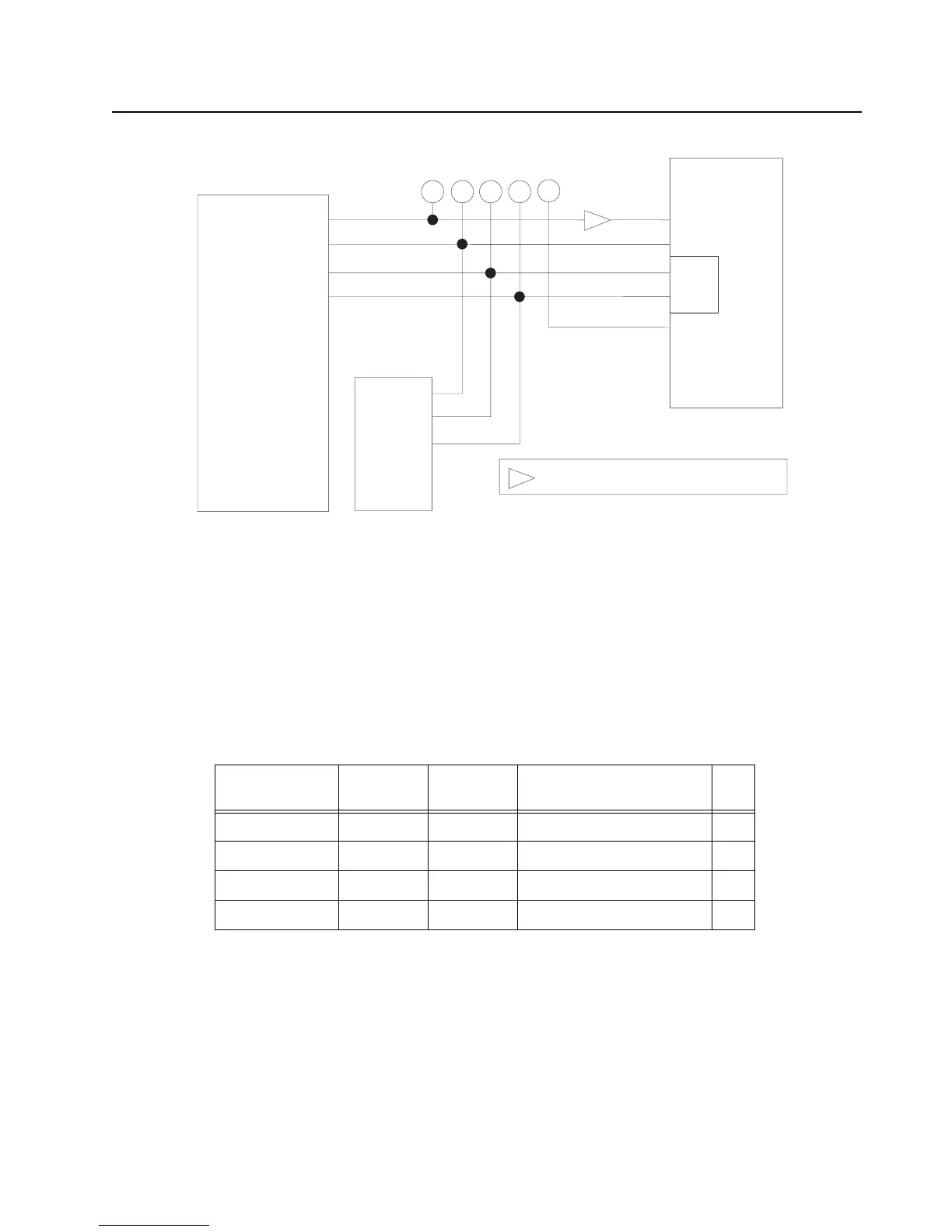
Figure 3-56. Bluetooth USB Interface Too Main VOCON
The ATMEL bootloader is being used as a first stage bootloader that will jump to the Motorola
bootloader, which is a stage two bootloader. GPIO20 is used by the ATMEL bootloader to trap in
Flash mode. GPIO19 will be used by the Motorola bootloader to trap in Flash mode. Both pins are
active low.
The Bluetooth audio is sent over a two-channel PCM/SSI interface to the audio codec (U6405) on
the VOCON board.
Table 3-19. GPIO I/O
Signal Name Pad Name GPIO Expansion Board
Schematic Name
I/O
GPIO41 PB09 41 BT_HOST_WAKEUP_3.3V I
GPIO49 PB17 49 BT_PTT_3.3V O
GPIO50 PB18 50 BT_SHUTDOWN_3.3V O
GPIO51 PB19 51 BT_WAKEUP_3.3V O
USB_BOOT
ATMEL_BOOT
APX 5000/ APX 6000/ APX 6000XE/ SRX2200
Expansion Board 80-pin Connector
JTAG Connector
ATMEL AVR32
AT32UC3A0512
PA19
VBUS
DP
DM
USB
PA20
C12
E12
D11
D12
D10
Pin 43
Pin 31
Pin 35
Pin 33
Pin 15
Pin 3
Pin 2
Factory Test Points
= Level Translator. 3.3 volts on AVR side

 Loading...


