2-2 Radio Power: DC Power Routing – Transceiver Board
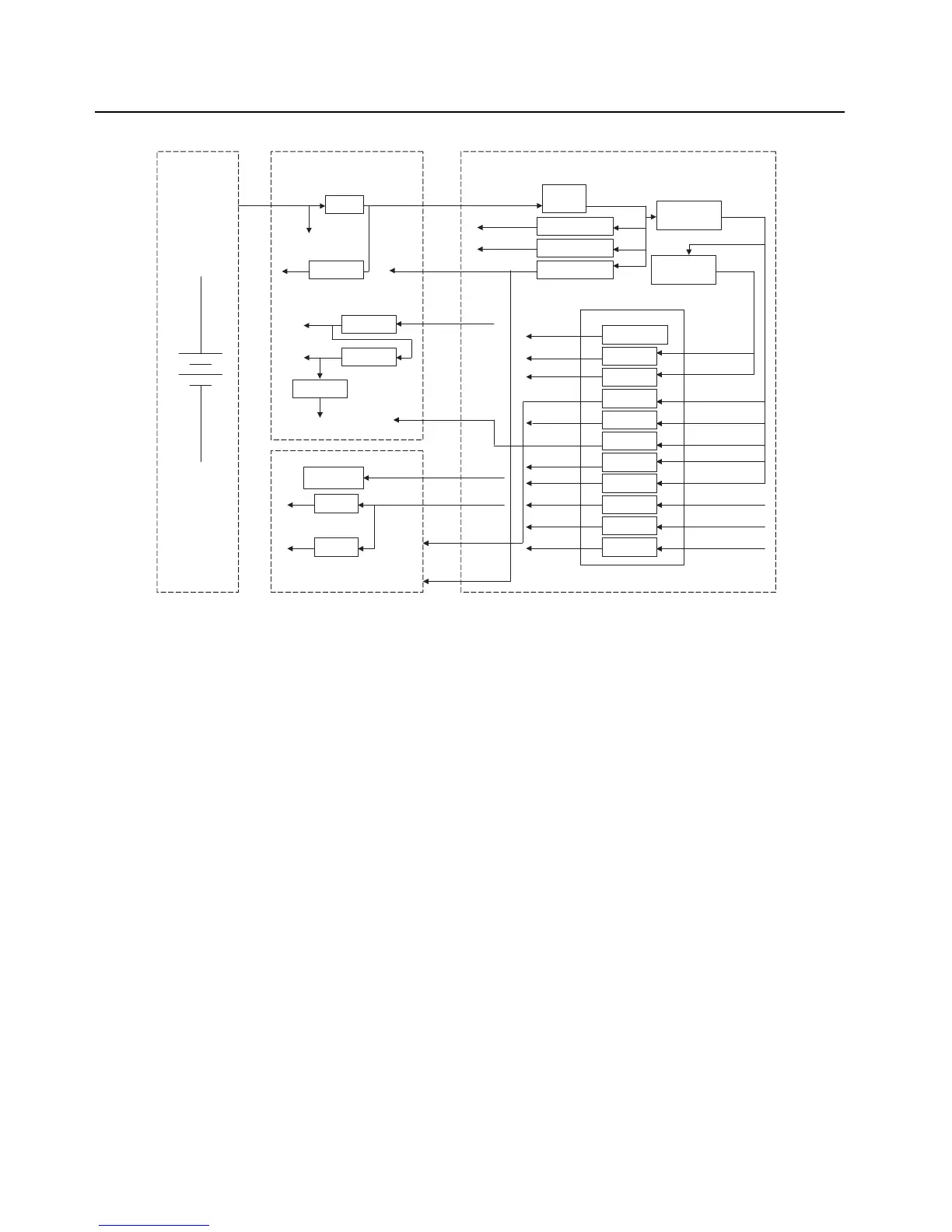
Figure 2-1. DC Power Distribution
B+ from the battery is electrically switched to most of the radio, rather than routed through the On/
Off/volume control knob, S2. The electrical switching of B+ supports a keep-alive mode. Under
software control, even when the On/Off/volume control knob has been turned to the Off position,
power remains on until the MCU completes its power-down, at which time the radio is physically
powered down.
2.2 DC Power Routing – Transceiver Board
NOTE: Refer to Table 8-1, “List of Transceiver Schematics and Board Overlays,” on page 8-1 for a
listing of schematics showing the transceiver board DC power routing components.
Connector M101, the B-plus assembly, connects the battery to the transceiver board. Component
E200 forms a power-line filter for signal DC_ RAW_B+, which supplies battery voltage to the
transmitter section. Fuse F200 and filter C202, L200, C203 supply fused B plus to the VOCON
board.
In turn, the VOCON board supplies VSW1 regulated 3.6 Vdc, 2.78 Vdc, and 1.85 Vdc. The
3.6 Vdc supplies regulator U201 and controls switch Q201 which supplies fuse B+ to regulator U200.
Regulator U201 supplies regulator U202 which in turn supplies regulator U203. The 2.78 Vdc
supplies the Trident IC U702, 16.8 MHz crystal circuit and Logic Expander IC U703. The 1.85 sets
the logic level for the SPI and SSI data.
The transceiver board has four regulators 5 Vdc (U200), 3 Vdc (U201), 1.8 Vdc (U202) and 1.5 Vdc
(U203). The 5 volt regulator supplies the FGU section, transmitter ALC and receiver back end. The
3 volt regulator supplies dc for the receiver front ends, mixer, receiver back end and GPS.
The 1.8 volt regulator supplies dc for the receiver front end and mixer. The 1.5 volt regulator supplies
dc for the buffers in the FGU section.
Fuse
5Vdc
3Vdc
Battery
7.5 Volts
(Nominal)
RF Board VOCON Board
1.8Vdc
1.5Vdc
BATT
M101
RAW B+
3Vdc
1.8 Volts
1.5Volts
P101
FB+
3.6Vdc
1.85Vdc
PMOS
Switch
SW_B+
MAKO
SW2
LD02
LDO3
LD04
LD06
LD07
LD09
LDO10
VBUS1
VBUS2
LD08
External SW
External SW
External LDO
1.875Vdc
1.55Vdc
2.775Vdc
2.775Vdc
2.8Vdc
2.8Vdc
3.0Vdc
3.3Vdc
5Vdc
5Vdc
5.4Vdc
1.4Vdc
1.85Vdc
External
LDO
3.6Vdc
2.23Vdc
5.4Vdc
5.4Vdc
SW_B+
2.23Vdc
5Vdc
FB+
3.6Vdc
3.6Vdc
3.6Vdc
2.23Vdc
3.6Vdc
External
SW
3.6Vdc
Expansion Board
1.85Vdc
3.6Vdc
5.4Vdc
5.4Vdc
2.775Vdc
Audio PA
3.3Vdc
2.8Vdc
3.3Vdc
2.8Vdc
5Vdc

 Loading...


