Chapter 7 Troubleshooting Tables
7.1 List of Board and IC Signals
Due to the nature of the schematic-generating program, signal names might be different when they
are not directly connected to the same point. The tables in this chapter provide a cross reference to
the various pinouts for these signals. Table 7-1 lists and provides links to each of the tables in this
chapter.
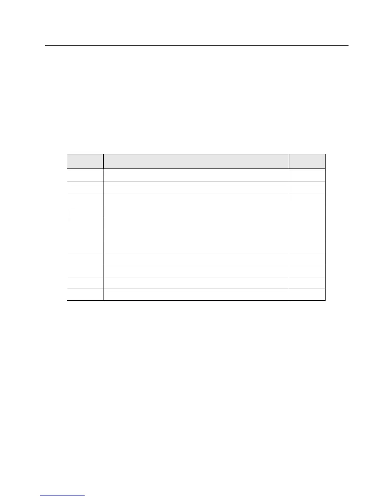
Table 7-1. List of Tables of Board and IC Signals
Table No. Table Name Page No.
7-2
VOCON board to RF board connector Interface PIN-OUT 7-2
7-3
VOCON board to EXPANSION board connector Interface PIN-OUT 7-4
7-4
VOCON board to Control Top with Top Display Interface PIN-OUT 7-7
7-5
VOCON board to Front Display Interface PIN-OUT 7-9
7-6
VOCON board to Keypad Interface PIN-OUT 7-10
7-7
EXPANSION board to Accessory Connector (GCAI) Interface PIN-OUT 7-11
7-8
EXPANSION board to Side Buttons Interface PIN-OUT 7-12
7-9
EXPANSION board to Speaker and Microphones Interface PIN-OUT 7-13
7-10
EXPANSION board to AVR / JTAG Interface PIN-OUT 7-14
7-11
Primary IC reference designators 7-15
7-12
Overall GPIO pin functions across multiple boards 7-16

 Loading...


