Theory of Operation: Accelerometer 3-63
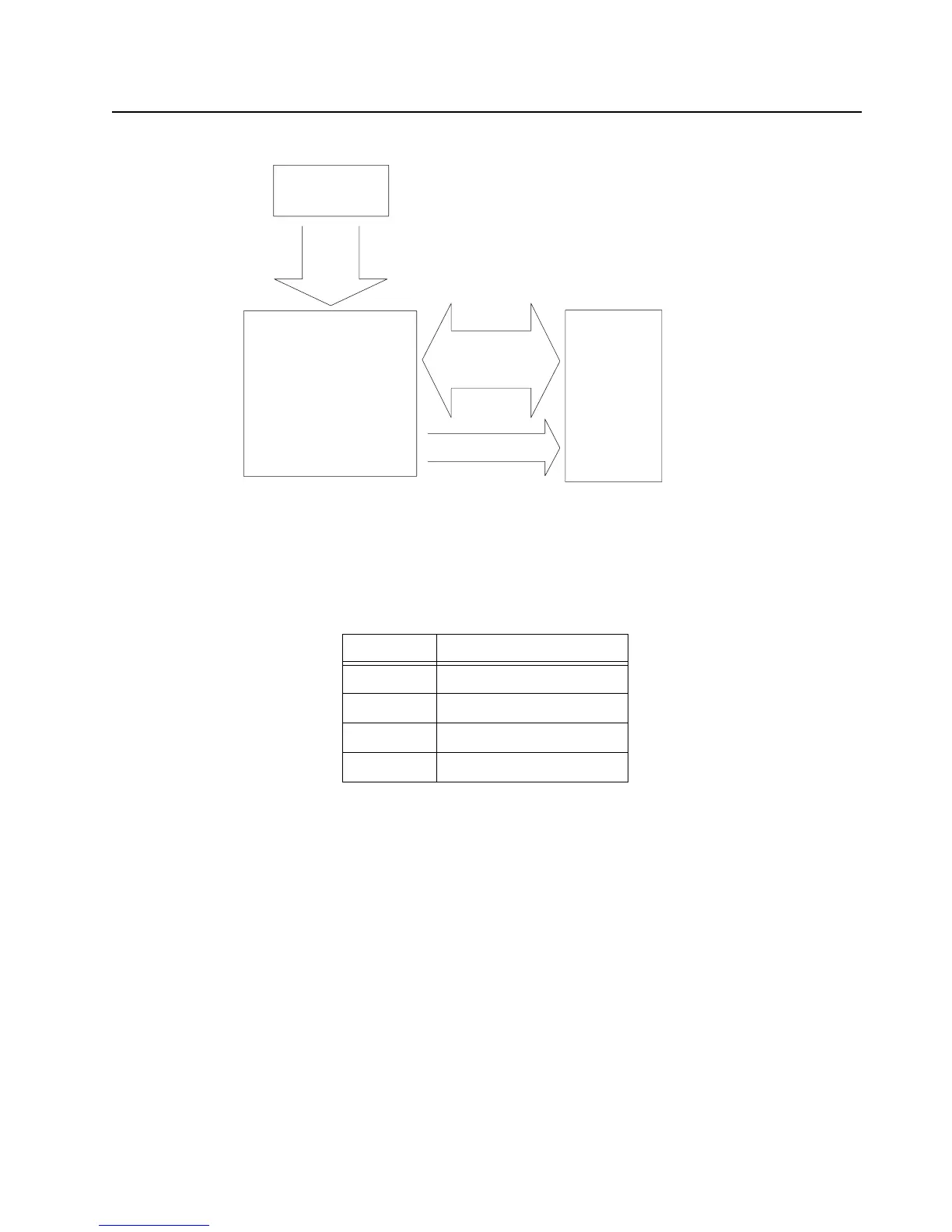
Figure 3-45. Accelerometer Block Diagram
The registers embedded on the LIS331DL are accessed through SPI serial interface. The following
pins are responsible for the SPI communication.
CS is the serial port enable and it is controlled by the AVR (SPI Master). It goes low at the start of the
transmission and toggles high at the end. SPC is the serial port clock and it is also controlled by the
AVR. It is stopped high when the CS is high (no transmission). SDI and SDO are respectively the
serial data input and output. These lines are driven at the falling edge of SPC and should be capture
at the rising edge of SPC.
Table 3-14. SPI Interface
Pin Name Pin Description
CS
SPI Enable
SPC SPI Serial Port Clock
SDI SPI Serial Data Input
SDO SPI Serial Data Output
3.3V LDO
Core
and
I/O
Voltage
Accelerometer
LIS331DLH
(Bus Slave)
SPI
Accelerometer
Data Bus
AVR
AT32UC3A
(Bus Master)
Interrupts

 Loading...


