Theory of Operation: Controller 3-41
3.2.4.10.3 ARM SPI
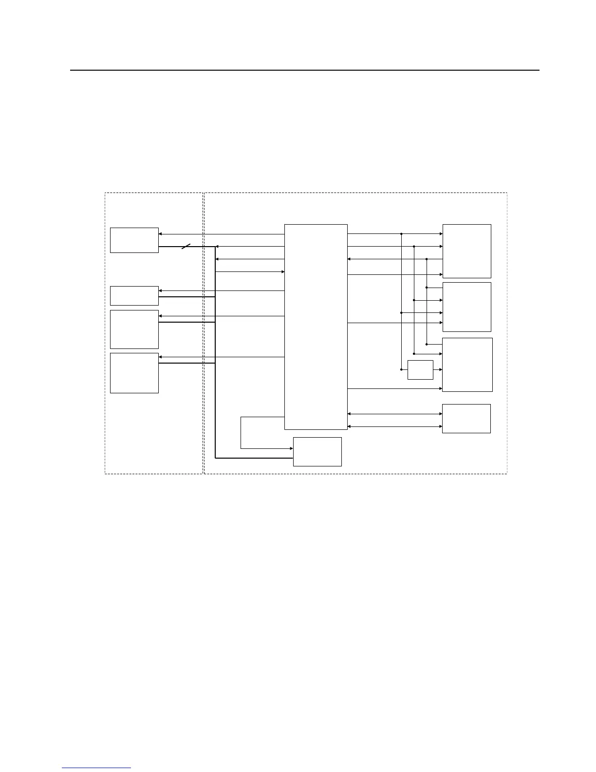
This SPI interface is controlled by OMAP's ARM core. Devices connected to this bus include MAKO,
display controllers and the audio CODEC.
3.2.4.10.4 DSP SPI
This SPI interface is controlled by the DSP core of the OMAP processor. This bus is used to
configure and control devices on the RF deck.
Figure 3-28. SPI and I2C Configuration
3.2.4.10.5 1-Wire
The OMAP's 1-wire line is available on the GCAI pin 16. The signal is routed to the side connector
via J4001.
3.2.4.10.6 USB
The OMAP CPU's USB port is routed to the side connector via J4001. The USB signals on the side
connector are illustrated in Figure 3-21, on page 3-34.
OMAP 1710
TOP DISPLAY
McBSP3 SPIF
DSP SPI
FRONT DISPLAY
MAKO
TI CODEC
ARM SPI
I2C
LIGHTING
CONTROLLERS
3
SPI_CLK
SPI_MOSI
SPI_MISO
MAKO_CS
TOP_DIS_CS
CPLD
Inverter
I2C_SCL
I2C_SDA
COLOR_DIS_CS
SPI_DSP_CLK
SPI_DSP_MOSI
SPI_DSP_MISO
DAC_CS
EEPROM_CS
ABACUS_CS
ABACUS_CS
DSP SPI
TRIDENT
ABACUS
EEPROM
DAC
RF BOARD
VOCON BOARD
CODEC_CS
I2C

 Loading...


