NXAMPMK2 USER MANUAL PAGE 49 / 80
OUTPUT PINS CONFIGURATION
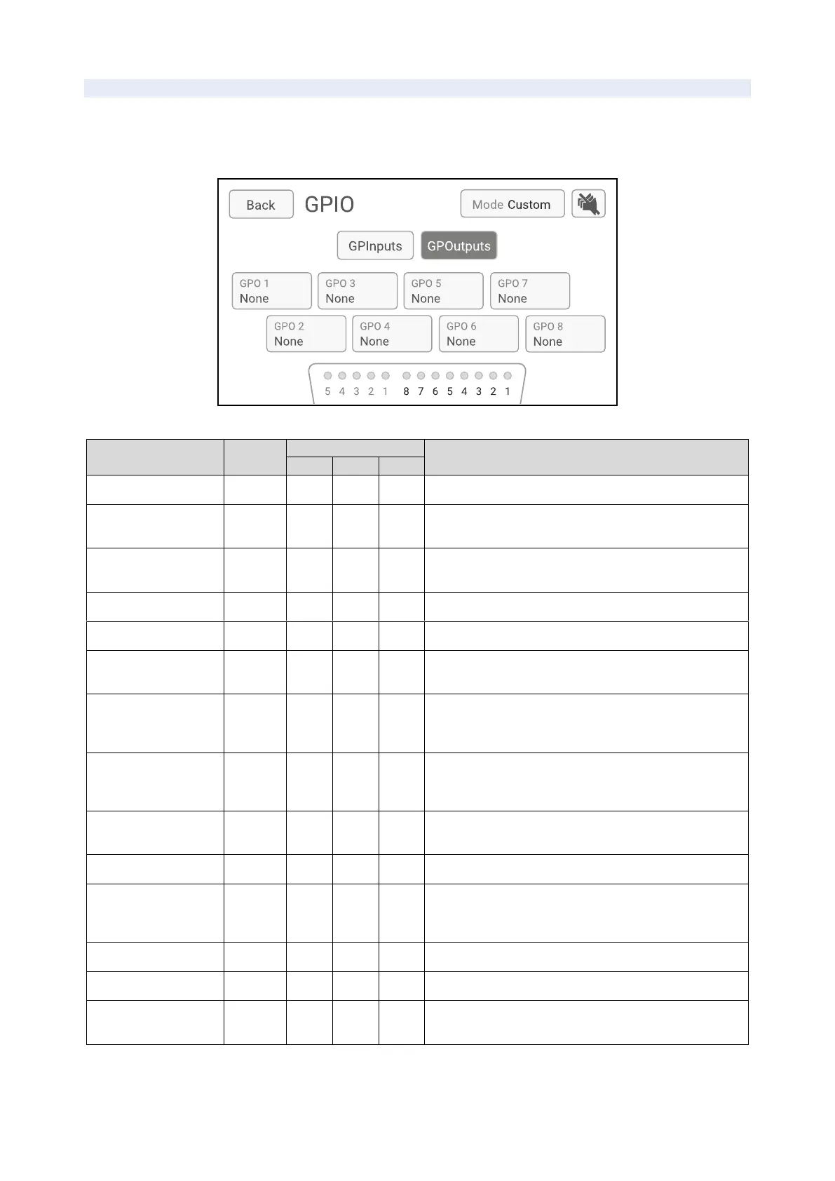
In Custom Mode, to configure the output pins (monitoring functions), press GPOutputs.
Outputs pins are numbered from GPO 1 to GPO 8. To configure an output pin, follow the same steps as
above for the input pins.
Low when amplifier is completely started.
The scene number selected has been recalled (applying
chosen polarity).
Analog inputs are muted. Does not apply when Analog
Fallback system is muting Analog Inputs.
Digital inputs are muted.
High when stand-by mode is OFF. Blinking when stand-
by.
High when maximum volume is reached on at least one
channel. Blinking when an increase command is
received.
High when minimum volume is reached on at least one
channel. Blinking when a decrease command is
received.
All channels are muted one by one, or overmute is
applied.
All the amplifier is attenuated by 20dB.
Reflects or invert the state of a GPInput (with small
delay and without glitch). For example, can be used to
forward a scene recall GPI to another amplifier.
Channel has output current.
Channel is reporting fault and is applying a protection.
Channel is muted individually. Does not consider
overmute.
 Loading...


