NXAMPMK2 USER MANUAL PAGE 59 / 80
The M3 cabinet can be connected using SPK8 only so it shows only arrow to this plug. Note that the M3 text
is displayed on both lines because it is an active speaker using both 3+/3- pair and 4+/4- pair of the SPK8
connector.
(2) Speaker Mode
For some setups, the mode is shown also on the display alternatively. For example, for our PS15R2 setup,
if you edit the setup for Channel 2 and select a monitor setup, the DPU display above will alternate with:
This information indicates that the PS15R2 to be connected on the first SPK4 should be a passive (PA)
cabinet, the one connected to the second SPK4 will be passive (PA) also but uses a Monitor setup.
For our Alpha example, the S2 and the B1-15 has no alternate information to display but the M3 output will
show that 3+/3- pins are connected to the MF whereas the 4+/4- are connected to the HF speaker of the
cabinet.
(3) Amplifier channel
The amplifier channel in use on each output is also shown alternatively with the displays above. For example,
in the four PS15R2 channels case:
And in our Alpha setup example:
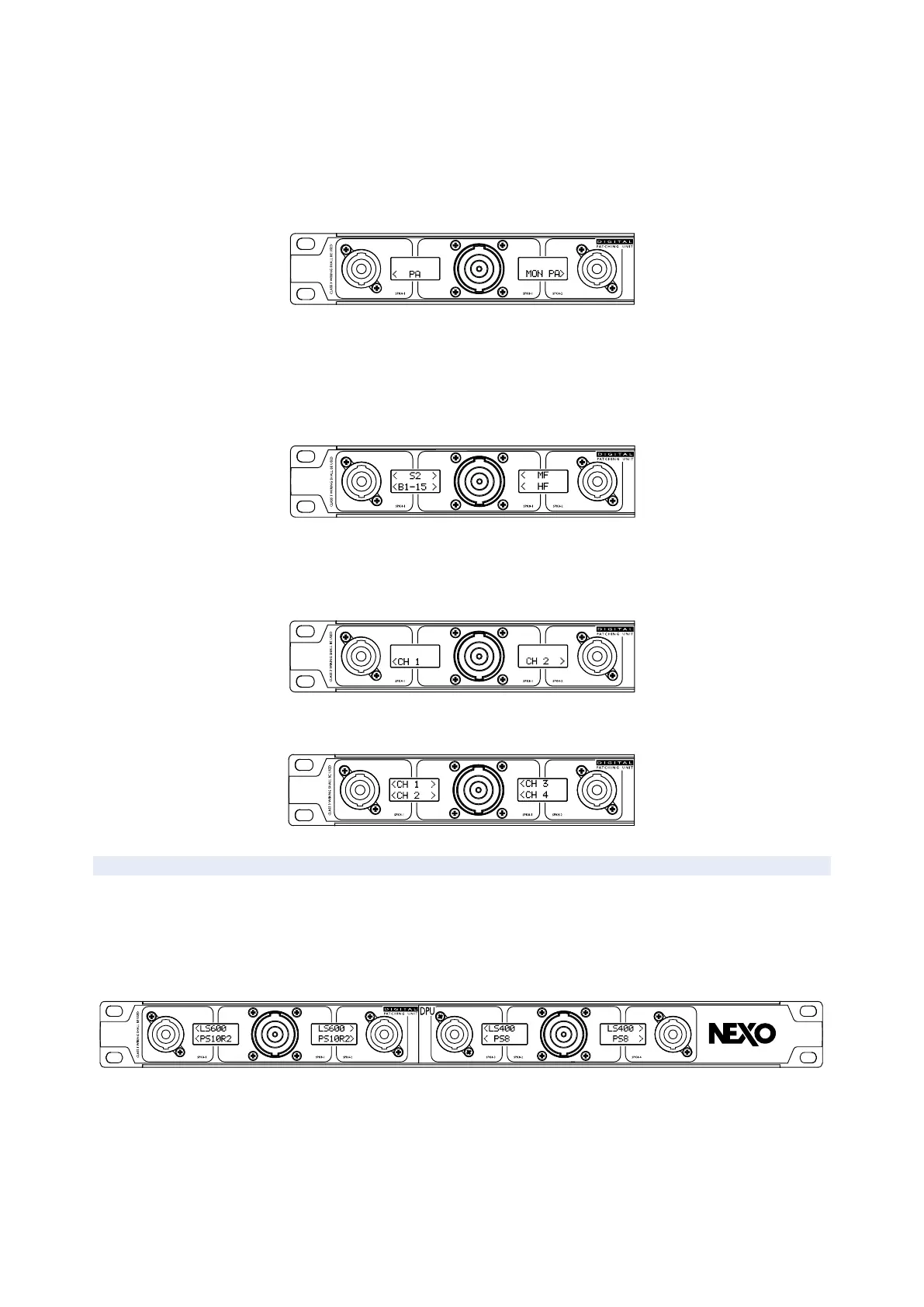
UNUSED FRONT PANEL CONNECTORS
The DPU will always try to use the maximum of outputs available to fit all the need of the user without
external adaptor or difficult cabling. Thus, sometimes the same channel is routed on several outputs.
Even if the DPU will never output a speaker signal on a wrong pinout, check the display information to be
sure to load the wanted amplifier channel.
In the bellow example, a setup using PS10R2/LS600/PS8/LS400 is selected.
Note that each amplifier channel is duplicated on several output, allowing to have the same cable to feed
PS (on 2+/2-) and LS (on 1+/1-) or use separate cable.
NB: In the example above, if you want to have PS10R2 and LS400 on the same cable, then a setup with
PS10R2/LS400/PS8/LS600 should be recalled.
 Loading...


