NB: A cable kit for DPU containing:
• 2 x 4 poles 4 x 4mm² speakON cable
• 1 x db9 crossover (null-modem) cable
• 2 x IEC mains cable with lockable connector (available with EU or US plugs)
can be purchased from NEXO separately.
OPERATING THE DPU
Using the DPU is straightforward, as there is nothing to set up. The only requirement is that the NXAMPmk2
firmware supports the DPU, otherwise it will stay in Stand-by mode with nothing patched on its front panel
connectors.
WARNING!
NXAMPmk2 firmware should be at least LOAD3_11 for the DPU to work. If not, the DPU will stay in stand-
by with nothing routed on its outputs
CONNECTIONS AND START UP
Be sure that the host NXAMPmk2 and the DPU are both disconnected from mains.
Connect the two four poles speakON cables between NXAMPmk2 (Speakon A and C) and DPU (Input A
and C) and connect the RS232 port between the NXAMPmk2 and the DPU using a crossover cable (see
serial port cabling above).
Then connect at least one IEC cable to one of the IEC mains inlets of the DPU. The left most display should
light -
Connect the NXAMPmk2 mains plug(s) and turn the NXAMPmk2
booting up; it should be LOAD3_11 or above.
After a few second the current selected speakers on the NXAMPmk2 are routed inside the DPU and their
names are displayed on the DPU screens.
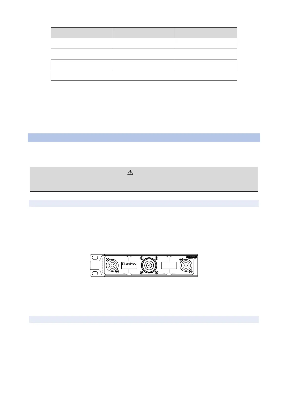
DPU FRONT PANEL CONNECTORS ROUTING
The front panel of the DPU is very symmetrical and shows two groups (one on grey background, the other
one on black background), both with two SPK4 and one SPK8.
For each of these blocks, the internal routing of SPK4 and SPK8 is done like on the bellow picture.
 Loading...


