7.
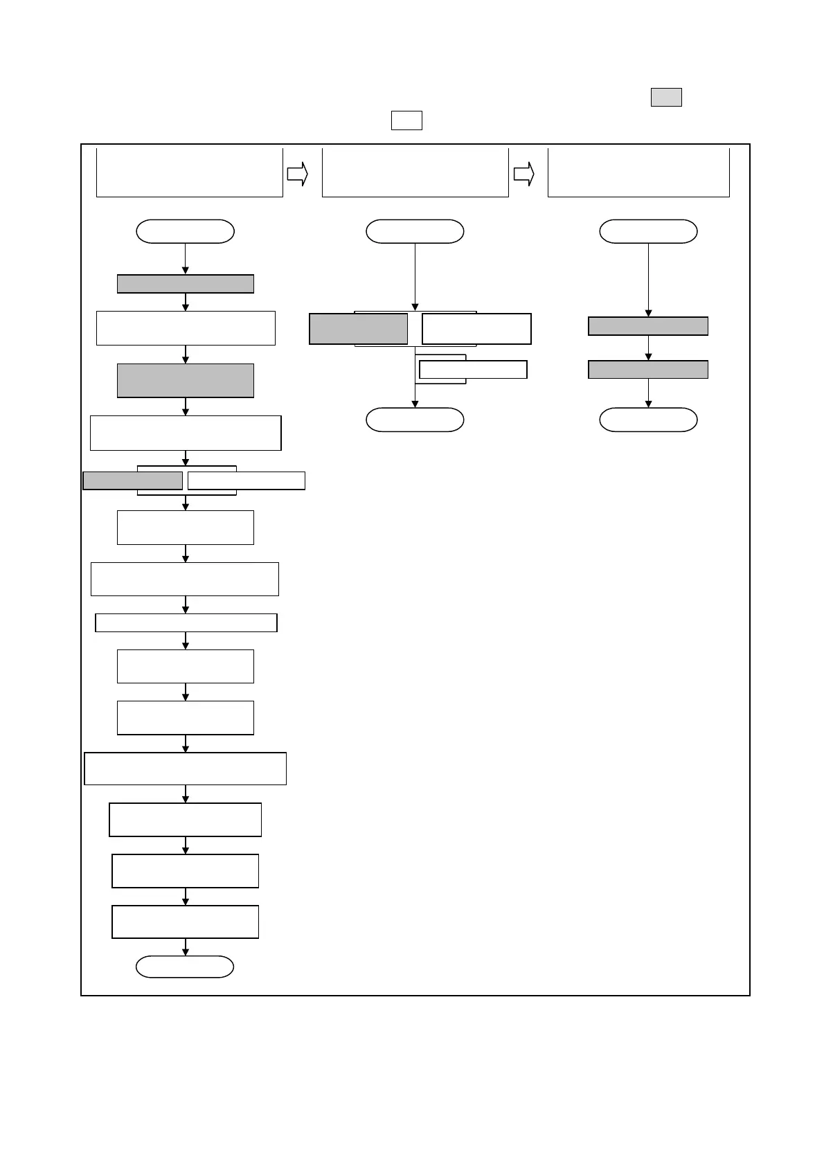
Operating Sequence (Flowchart)
An operation flowchart is shown below. The Basic operation steps are shown in the shaded boxes.
For advanced operations, the steps shown in the boxes are also required.
1. Initial Settings are Designated.
2. Switch Output Setting are
Designated.
3. Operation is Executed.
Initial setting No. are shown in parentheses.
START
Switch power ON
If using the VS-5EX Model,
designate the output specifications
Sensor rotation
direction setting
Designate whether or not origin point
is to be set by an external input
Origin point setting Current position setting
Designate the program
No. input format
Designate whether or not the Protected
Switch function is to be used
Cancel the Protected Switch function
Designate the SET
mode output status
Designate the number
of timing pulses
Establish a status, which permits
settings to be changed during operation
Designate the current position
output’s latch pulse cycle
Establish a “communication
data setting enabled” status
Designate the communication
baud rate
END
START START
Setting designated
by “angle” input
Delete the setting
END
Program No. input
Begin operation
END
(02)
(01)
(03)
(98) (99)
(97)
(96)
(95)
(94)
(93)
(92)
(91)
(89)
(81)
(Not required for VS-5E)
(When using the VS-5EX)
●C-1●
Setting designated
by TEACH function
Artisan Technology Group - Quality Instrumentation ... Guaranteed | (888) 88-SOURCE | www.artisantg.com
 Loading...