8-2.
Sensor Rotation Direction Setting
Designate the sensor rotation direction in which the angular value is to increase.
Set the key-switch to the INIT position.
Set the mode selector key-switch to the INIT position in order to
designate the rotation direction.
Enter the initial No.
01
SWITCH
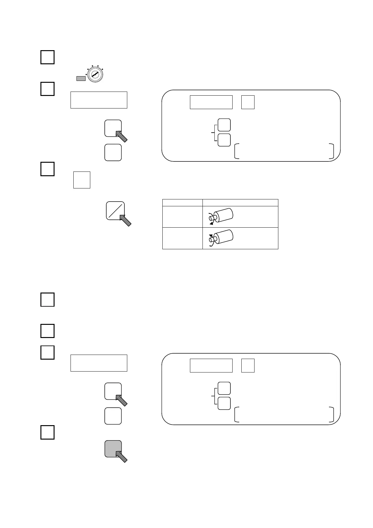
Designate the setting content.
0
DOG
Setting Value Description
0
CW direction
1
CCW direction
8-3.
Origin Point Setting
Move the machine to the desired origin point position and designate that position as the origin point. The
key-switch should be left at the INIT position for this operation.
Verify that the Absocoder sensor is connected.
If not connected, a “sensor error” will occur, and setting will be
impossible.
Move the machine to the origin point position.
Designate initial No.”99”.
99
SWITCH
Press the [set] key.
At this time, “000” will be indicated at the POSITION display,
and the origin setting operation is completed.
1
11
1
2
22
2
3
33
3
1
11
1
2
22
2
4
44
4
SET
SETSET
SET
3
33
3
┼
─
00
PROGRAMSWITCH DOG
Switch No.
←
Press this key to increase the displayed No.
(Initial No.)
[+/-] keys. ←Press this key to decrease the displayed No.
However if this key is pressed when “00”
is dis
la
ed
“99” will be dis
la
ed.
┼
─
Each time the [ON/OFF] key is pressed, the
display will alternate between “0” and “1”.
┼
─
SET
TEACH
CLEAR
INIT
RUN
●C-3●
ON
ONON
ON
OFF
OFFOFF
OFF
00
PROGRAMSWITCH DOG
Switch No. ←Press this key to increase the displayed No.
(Initial No.)
[+/-] keys. ←Press this key to decrease the displayed No.
However if this key is pressed when “00”
is dis
la
ed
“99” will be dis
la
ed.
┼
─
Artisan Technology Group - Quality Instrumentation ... Guaranteed | (888) 88-SOURCE | www.artisantg.com
 Loading...