10.
Errors
Error causes and countermeasures are described below.
10-1.
Error Displays & Countermeasures
When a Controller or Sensor error occurs, there will be an error display, and an error signal output. When
this occurs, refer to the following Table to determine the cause and the appropriate countermeasure.
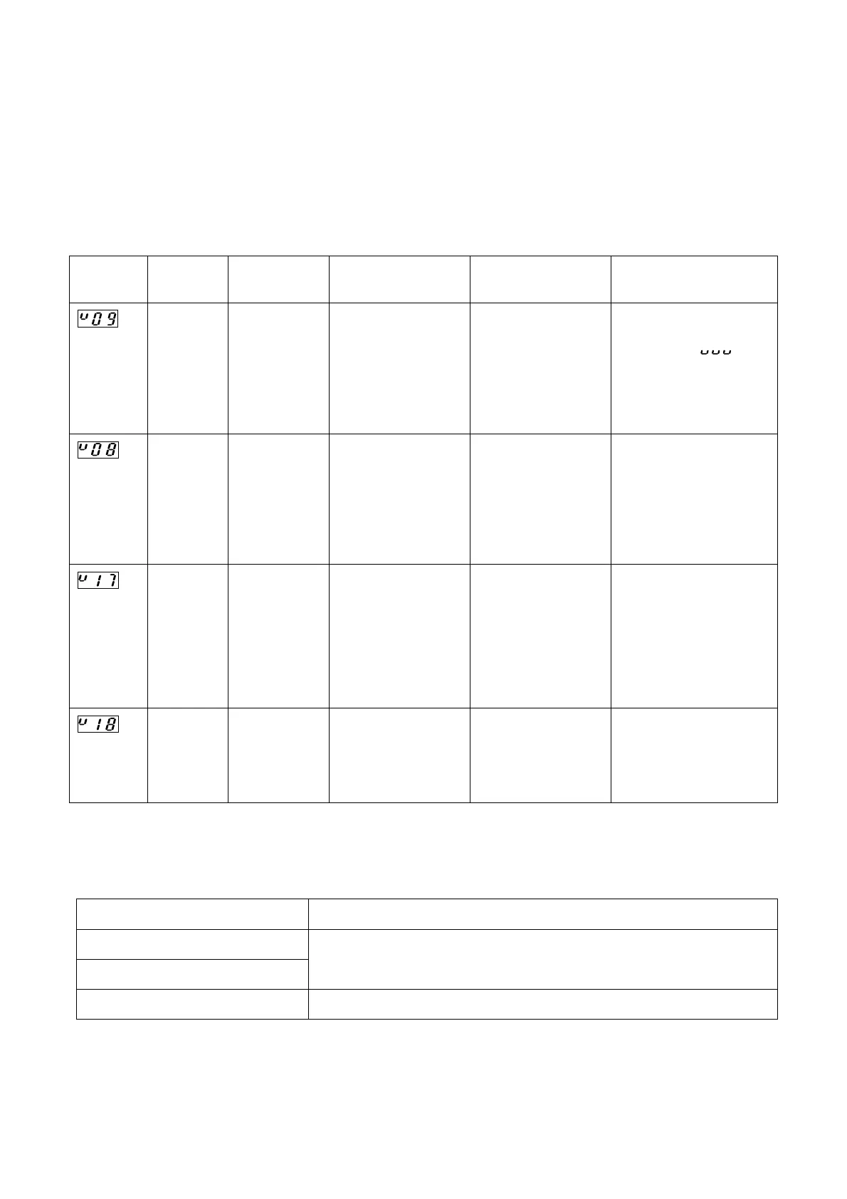
● Error Displays, Causes, & Countermeasures Table
Error
Display
Name Output Status Probable Cause Countermeasure Error Cancel Procedure
flashing
display
“NOR.”
LED is
OFF
Memory
error
Switch outputs
OFF
Timing pulse
output
OFF
System Ready
output
OFF
Memory data has
been changed to due
external noise, etc.
Cancel the error, and
re-designate the
settings beginning
from the initial
settings.
Press the [ON/OFF] key.
All setting data will be
deleted, and [
] will
be displayed.
flashing
display
“NOR.”
LED is
OFF
Sensor
error
Switch outputs
OFF
Timing pulse
output
OFF
System Ready
output
OFF
1) Sensor connector
is disconnected or
loose.
2) Position sensor
hardware
malfunction.
1) Correct the error
cause.
2) If caused by a
Sensor or Controller
malfunction, replace
the malfunctioning
unit.
After correcting the error
cause, press the
[ON/OFF] key.
is flashing.
“No setting”
error
During the switch
output setting
operation, an ON
setting was
designated without
designating the
corresponding OFF
setting.
Cancel the error,
and, after
re-designating the
ON position setting,
designate the OFF
position setting.
Press the [ON/OFF] key.
is flashing.
Setting
error
The position where a
setting was
attempted is outside
the permissible
setting range.
Cancel the error and
designate a correct
setting.
Press the [ON/OFF] key.
10-2.
Setting Procedures After Replacing Sensor/Controller
After replacing the Sensor or Controller, the following setting items must be designated.
Item Replaced Setting Required
Sensor
Cable
Re-designate the origin point setting.
Controller All setting items must be designated.
●C-22●
Artisan Technology Group - Quality Instrumentation ... Guaranteed | (888) 88-SOURCE | www.artisantg.com
 Loading...