9.
Advanced Operation
9-1.
Initial Settings
In order to use the VALICAM functions, those required functions must first be designated at the initial
settings. In this section, the initial setting procedure will be explained.
In the Initial Setting List shown below, the factory setting values (default values) are shown in [ ]. Unless
another setting is desired, these setting items can be skipped.
9-1-1.
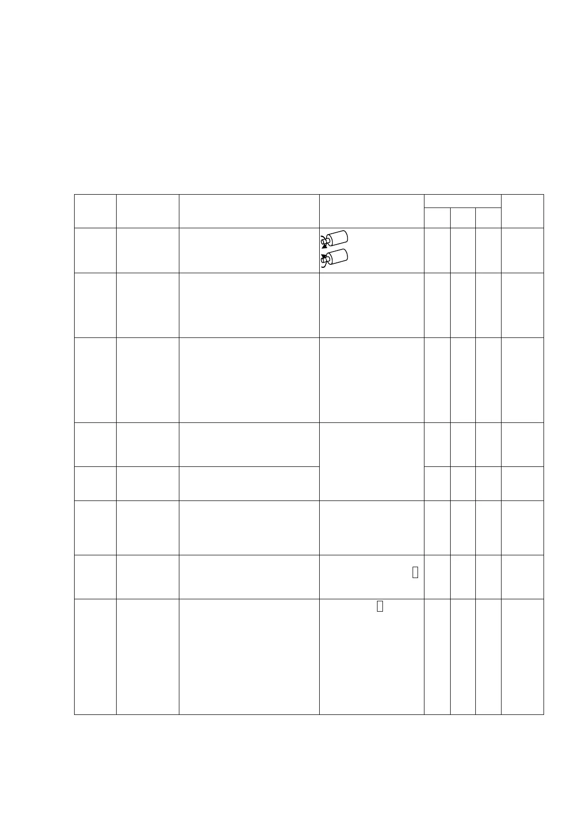
Initial Setting List
Applicable Model
Initial No.
Item Description Setting
VS-5E VS-5ED VS-5EX
Setting
Procedure
page No.
01
Sensor rotation
direction
Designate the sensor rotation
direction in which the current
position value is to increase.
CW direction:[0]
CCW direction:1
○ ○ ○
8-2
02
VS-5EX output
specifications
Select either the “16-Program,
40-Switch” or the “32-Program,
24-Switch” format. When using the
VS-5EX Model, this setting should
be designated first, immediately
after delivery.
16-Program,
40-Switch: [0]
32-Program,
24-Switch: 1
○
9-1-3
03
“Current
position
HOLD/External
origin set”
selection
- Designate which of these functions
is to be used. (Both functions
cannot be designated.)
- When the “External origin set”
function is selected, setting
changes cannot be made during
RUN operation.
(Refer to Initial No.92.)
Current position
HOLD: [0]
External Origin
Set : 1
○
9-1-2
99
Origin point
setting
Rotate the sensor to the desired
origin point position and designate
that position as the origin point
(000).
○ ○ ○
8-3
98
Current
position setting
The current position value for any
desired sensor position can be
designated by entering that value.
Setting must be designated
by one of these 2 formats.
○ ○ ○
9-1-6
97
Program No.
input format
Designate the format to be used for
selecting the No. of the Program to
be run.
By panel key input: [0]
By external connector
input: 1
By serial
communication: 2
See
note
○ ○
9-1-2
96
Protected
switch
Designate whether or not the
Protected Switch function is to be
used. The Protected Switch function
can be used for Switch Nos. 1-10.
protected Switch function
INVALID: 0
VALID: 1
○ ○ ○
9-1-4
9-1-5
95
Protected
Switch Cancel
This setting is designated to cancel
the Protected Switch function so that
the Protected Switch setting value
can be changed. Immediately after
canceling the Protected Switch
function, the key-switch should be
set to the SET or TEACH position in
order to change the setting value. If
the key-switch is set to the RUN
position, the “cancel” command will
be invalid.
Do not cancel: 0
Cancel: 1
○ ○ ○
9-1-2
Note: To change a setting value by serial communication during operation, a setting of “2” is required.
●C-7●
Artisan Technology Group - Quality Instrumentation ... Guaranteed | (888) 88-SOURCE | www.artisantg.com
 Loading...