5-8
Installation in a Control Panel
When the Sensor Controller is being installed in a cabinet or control panel, be sure to provide proper
ambient conditions as well as access for operation and maintenance.
5-8-1
All Series
Precautions for Safe Use
Installation Environment
• Do not use the product in the environment with flammable or explosive gases.
• Install the product so that the air can flow freely through its cooling vents.
• Regularly clean the vent holes or fan outlet to prevent dust or particles blocking them. Internal
temperature increases when those are blocked, it causes malfunction.
• To secure safety for operation and maintenance, install the product apart from high-voltage
devices and power devices.
• Make sure to tighten all screws in mounting.
Accessibility for Operation and Maintenance
• Do not apply torsion stress to cables. If not, it may cause damage to cables.
• Secure the minimum bending radius of cables. If not, it may cause damage to cables.
Precautions for Correct Use
Installation and Storage Sites
Install and store the product in a location that meets the following conditions:
• No rapid changes in temperature (place where dew does not form)
• No presence of corrosive or flammable gases
• Place free of dust, salts and iron particles
• Place free of vibration and shock
• Place out of direct sunlight
• Place where it will not come into contact with water, oils or chemicals
• Place not affected by strong electro-magnetic waves
• Place not near to high-voltage, or high-power equipment
Ambient Temperature
• Do not install the product immediately above significant heat sources, such as heaters, trans-
formers, or large-capacity resistors.
Noise Resistance
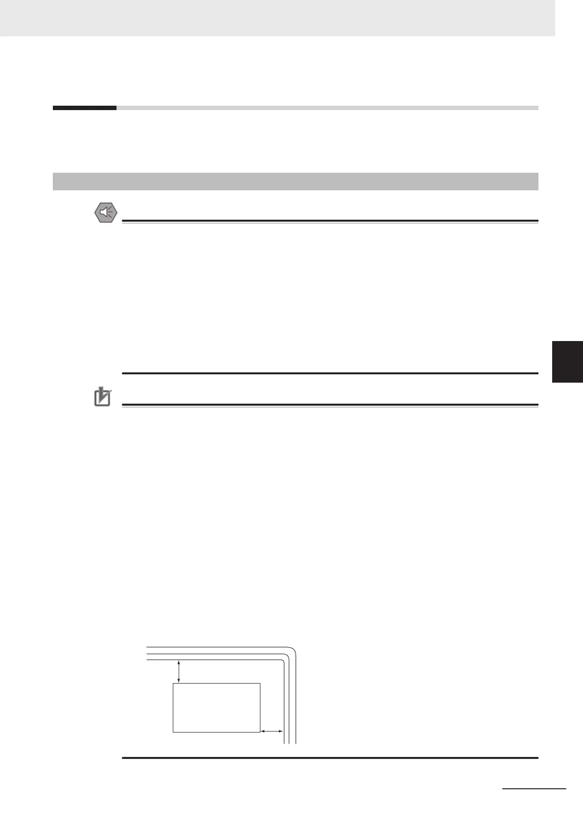
• Do not install the Sensor Controller in a cabinet with high-voltage equipment installed.
• Mount the Sensor Controller at 200 [mm] or more from power cables apart.
Sensor
Controller
200 mm min.
200 mm min.
Power lines
5 Setup and Wiring
5-29
FH Series Vision System Hardware Setup Manual (Z366-E1)
5-8 Installation in a Control Panel
5
5-8-1 All Series
 Loading...


