6-4-3
Pin Layout
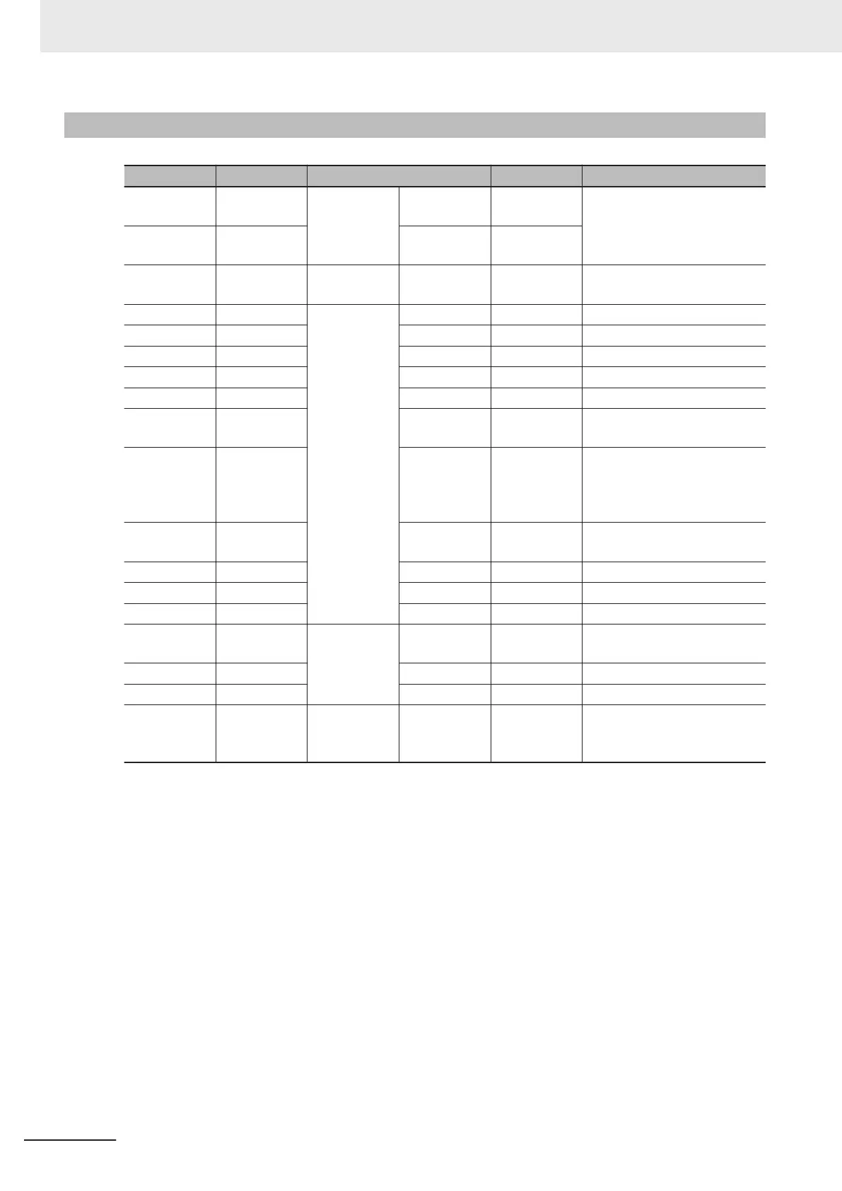
Wire Color Mark Part Signal Name Function
Brown (Heavy
gauge)
None
Power suply
- 24 VDC
External power supply
(24VDC)
Blue (Heavy
gauge)
None - 0V
Black (Heavy
gauge)
None Ground - FG Ground
White Black
I/O
- COMIN Common for input signals
Pink Black - COMOUT Common for output signals
Orange None OUT ERROR ON when there is an error
White None OUT OR Overall Judgement Result
Yellow None OUT BUSY Processing in progress
Purple None OUT READY
ON when Image input is al-
lowed
Black None OUT
STGOUT/
SHTOUT
STGOUT: Strobe trigger sig-
nal
SHTOUT: Shutter output sig-
nal
Red None IN DI2
Serial Data
※ DI7 (Run) during operation.
Green None IN DI1 Serial Data
Gray None IN DI0 Serial Data
Pink None IN STEP Measurement trigger input
Green Black
RS-232C
OUT
RS-232C
OUT
RS-232C Data transmit
Purple Black IN RS-232C IN RS-232C Data receive
Light blue Black - RS-232C 0V RS-232C GND
Black (heavy
gauge)
None - - FG
Not used (do not touch other
power lines, grounding lines,
and signal lines.)
6 Power Supply and I/O Interface
6 - 8
FHV Series Smart Camera Setup Manual (Z408-E1)

 Loading...


