60 LD Platform OEM User's Guide 11970-000 Rev H1
6.2 Payload Bay Connections
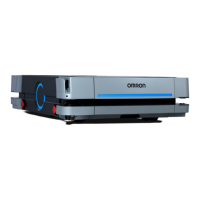
NOTE:Standard connectors, such as audio, are not covered here. This includes all
of the connectors on the right side of the core, shown in the following figure:
Digital
Ant1
Ant2
Audio In
Audio Out
Audio Out
Figure 6-1. Right Side of the Core
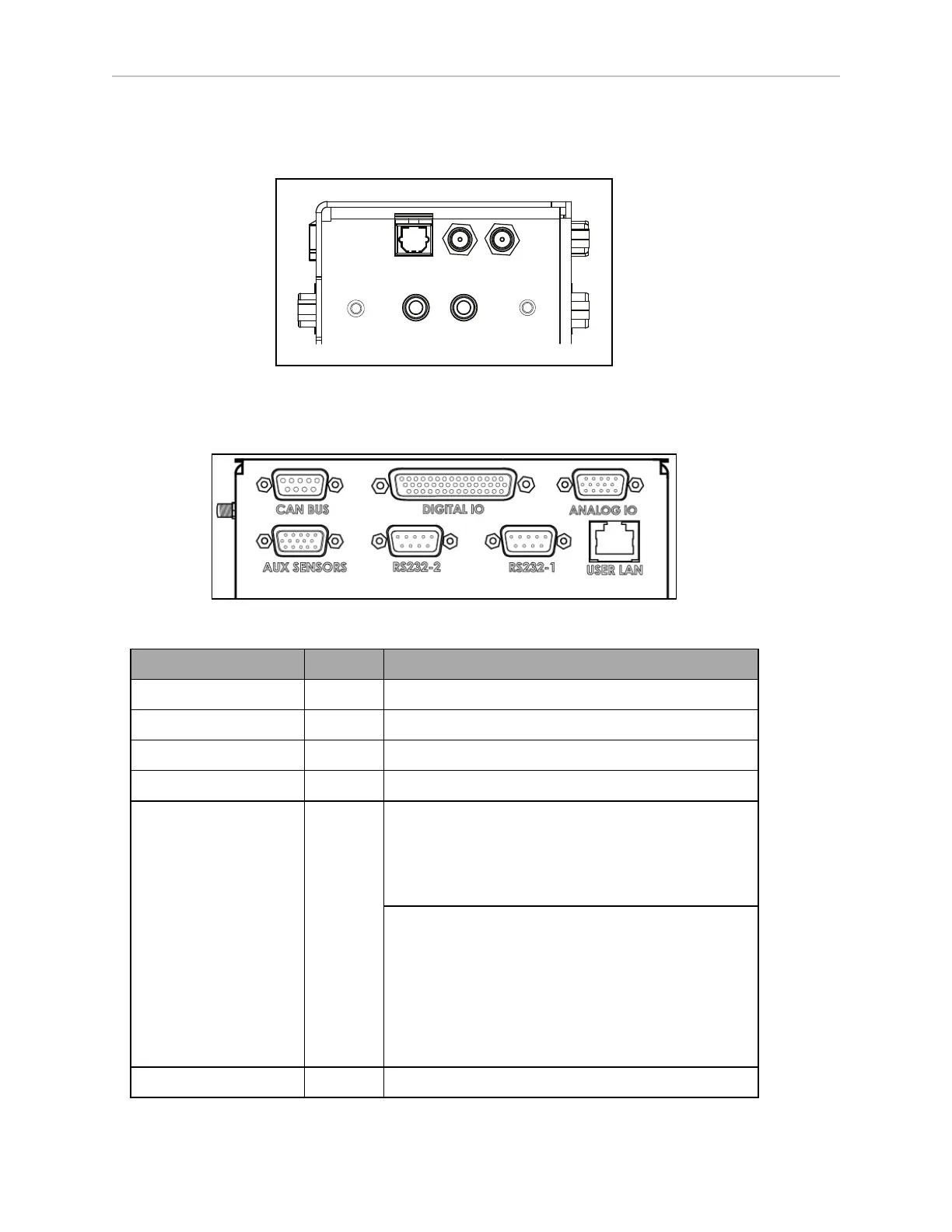
LD Platform Core Front, Upper
Figure 6-2. Front Upper Core
Connection Type Description
User LAN RJ45 General Ethernet, Auto-MDIX, shielded
Aux Sensors HDB15M Low front and optional side lasers
RS-232 x 2 DB9M Port 1 and Port 2, general use
CAN Bus B DB9F Consult your local Omron Support for use.
Digital I/O (HDB44F) HDB44F 16 digital inputs, in 4 banks of 4. Each bank can be
wired as active high or active low depending on the
connection of the BANK# terminal.
V
IN
range for each input is 0 to 30 V. The input is ON
when V
IN
> 4 V, OFF when V
IN
< 1.3 V.
16 digital outputs, protected low-side drivers. These
outputs should be wired to positive voltage through
the load. Output is open when OFF and grounded
when ON. Each open-drain output is capable of sink-
ing 500 mA. May be used with loads connected to
VBAT, AUX_20V, _12V, or _5V. You must stay
within the allowed current capacity of the VBAT or
AUX power supplies.
Analog I/O HDB15M General use
 Loading...