Wiring for Forward Rotation Pulse/Reverse Rotation Pulse (d14 = 1)
Connect the forward rotation pulse/reverse rotation pulse as shown in the diagram below.
• Connect the forward rotation pulse to the pulse train input PIA terminal and the reverse rotation
pulse to the pulse train input PIB terminal.
• The +24 V terminal of the inverter control circuit terminal block is for a 100 mA maximum 24 V pow-
er supply
. This terminal can be used for the encoder power supply if the consumption current for the
input terminals in use and the encoder power supply is allowable. However, note that this terminal
must be isolated from any 24 V system power supply for other than the encoder and inverter.
2-3-7
Wiring for RS-485 Communications Terminal Block
This inverter has RS-485 communications terminals on its control circuit terminal block.
It uses the Modbus communication protocol to establish communications with external controllers.
This section describes the wiring procedure for the RS-485 communications terminal block and the in-
stallation of the terminating resistor
.
Wiring for RS-485 Communications Terminal Block
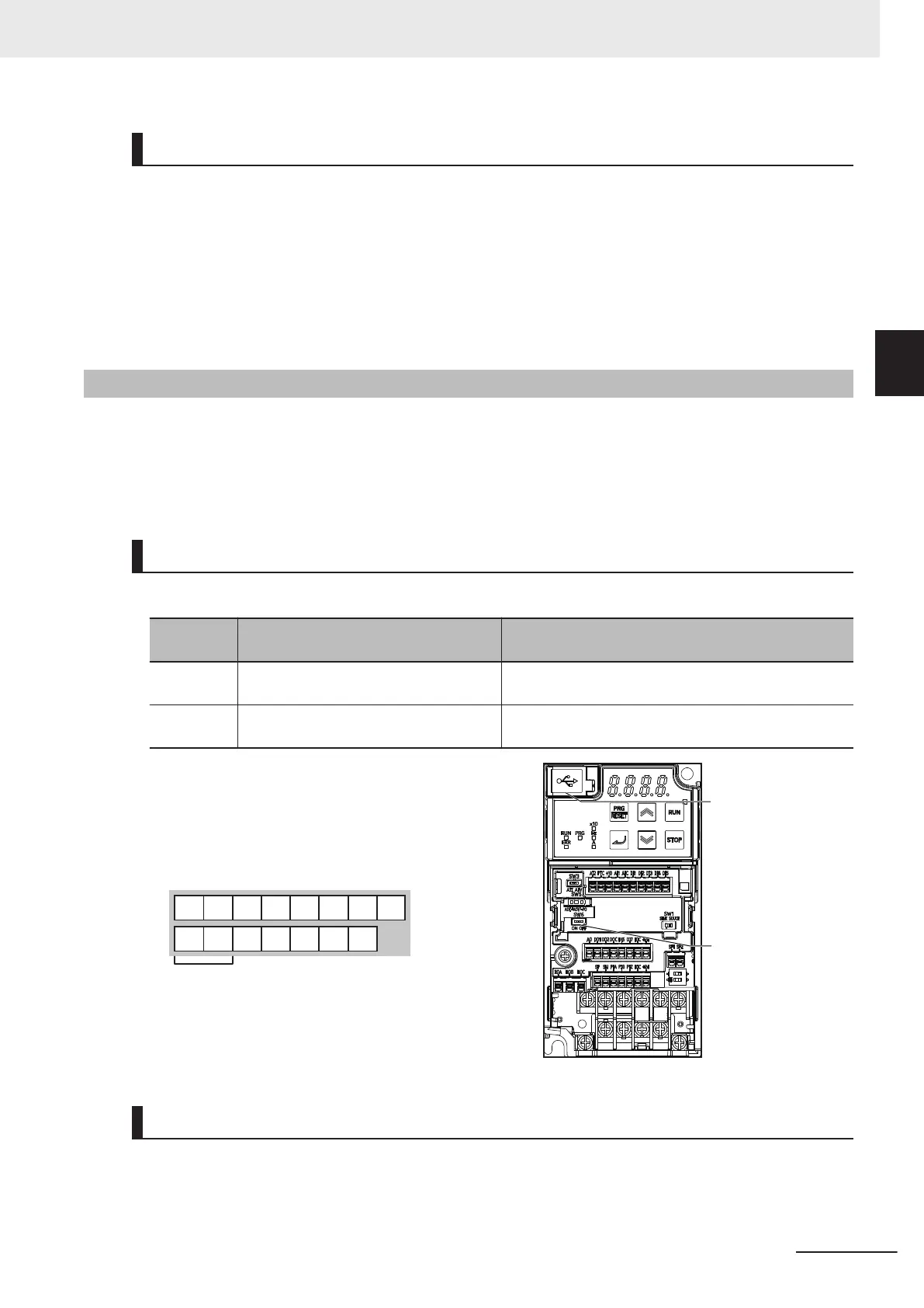
On the control circuit terminal block, the following RS-485 communications terminals are provided.
Terminal
symbol
Terminal name Function
SN Modbus terminal (RS-485) Negative-side send/receive terminal for RS-485 com-
munications.
SP Modbus terminal (RS-485) Positive-side send/receive terminal for RS-485 com-
munications.
+24DI7 DICDOC DI6DO2
AO
DO1
DIC +24PIB PIZPIA
SP
SN
Communications
RS-485
U
SB port is
intended for
computer only.
RS-485 (RJ45
modular
connector) port is
for Digital Operator
use only.
Terminating
resistor selector
switch (SW6)
Terminating Resistor Setting
Connect the inverters parallel to each other as shown below and, only on the terminal inverter, turn
ON the terminating resistor selector switch.
Even if you have only one inverter connected, turn ON the terminating resistor selector switch.
2 Design
2-57
M1 Series Standard Type User's Manual (I669)
2-3 Wiring
2
2-3-7 Wiring for RS-485 Communications Terminal Block
 Loading...


