4-2
List of Parameters by Group
The parameters that are displayed are limited by the setting of Operator (Menu display mode) (E52).
To display all parameters, set Operator (Menu display mode) to “2: Full menu mode.” (The default set-
ting for Operator (Menu display mode) (E52) is “2: Full menu mode”.)
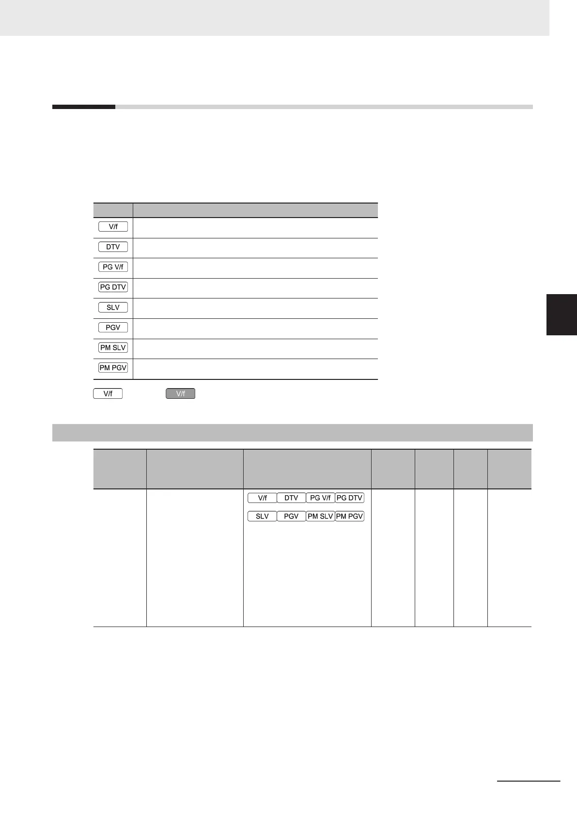
Enabled and disabled states for each control mode within the data range of the parameters are indi-
cated by the icon.
Symbol Control method (F42/A14)
0: IM V/f control
1: IM Dynamic torque vector control
3: IM V/f control with speed sensor
4: IM Dynamic torque vector control with speed sensor
5: IM Vector control without speed sensor
6: IM Vector control with speed sensor
15: PM Vector control without speed and pole position sensor
16: PM Vector control with speed and pole position sensor
: Enabled : Disabled
4-2-1
Parameter F (Basic Functions)
Parameter
No.
Function name Monitor or Data Range
Default
data
Setting
during
RUN
Unit Page
F00
Operator Protection
Function Selection
0: Disable parameter protec-
tion, enable Up/Down keys
1: Enable parameter protec-
tion, enable Up/Down keys
2: Disable parameter protec-
tion, disable Up/Down keys
3: Enable parameter protec-
tion, disable Up/Down keys
0
Availa-
ble
-
page
7-74
4 Parameter List
4-77
M1 Series Standard Type User's Manual (I669)
4-2 List of Parameters by Group
4
4-2-1 Parameter F (Basic Functions)
 Loading...


