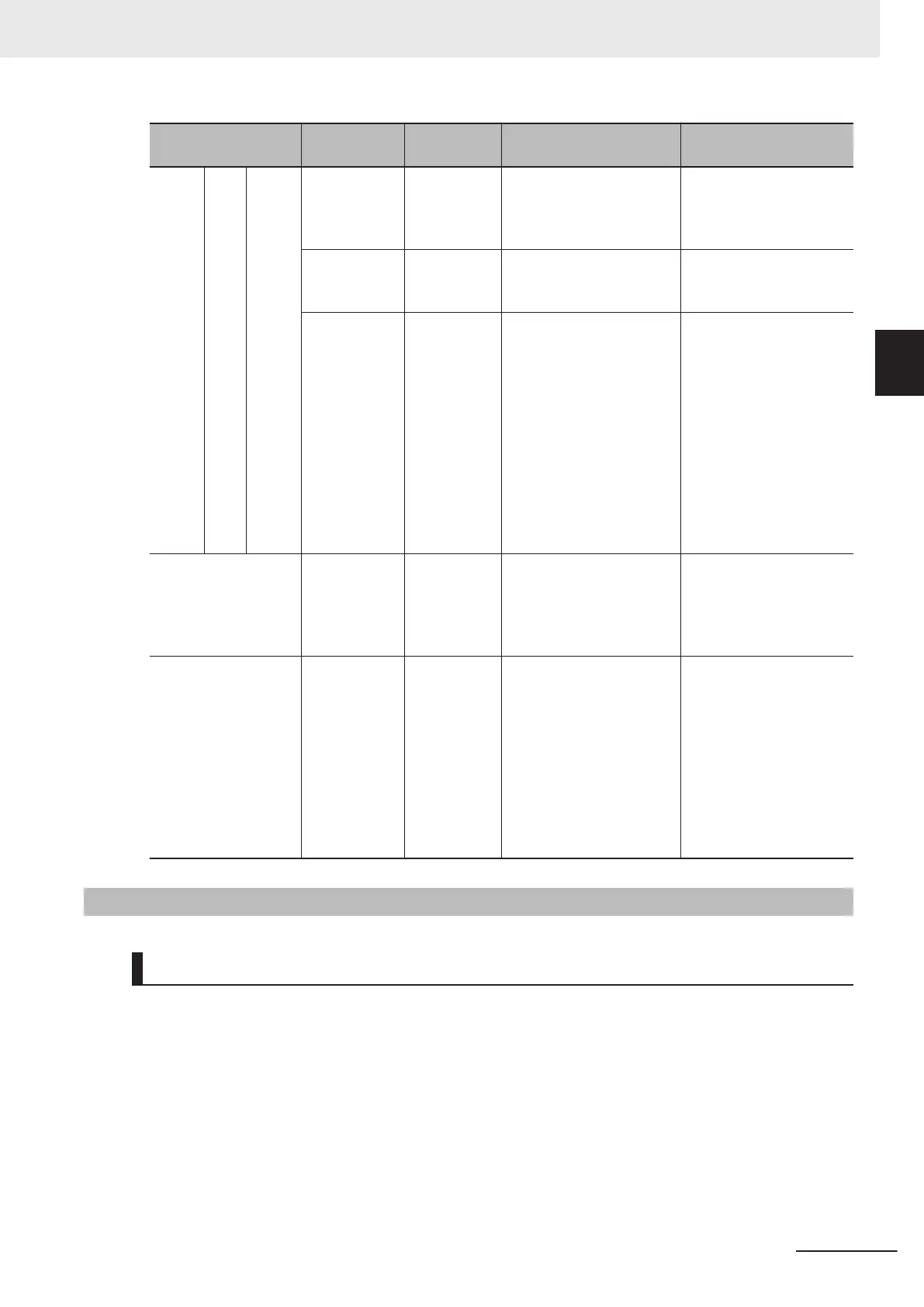
Item
Terminal
symbol
Terminal
name
Description Specifications
Digital Out-
put
Open
collec-
tor
+24 Power sup-
ply terminal
for output
signal
This is a 24 VDC power
supply for the output sig-
nal.
Allowable current: 100
mA max.
DOC Output signal
common
Common terminal for mul-
tifunction output terminals
DO1 and DO2.
Allowable current: 100
mA max.
DO1
DO2
Multifunction
output termi-
nal
Select 2 functions from
among 92 functions, and
allocate them to terminals
DO1 and DO2. These ter-
minals support both the
sink logic and the source
logic. For details on the
connection, refer to Multi-
function Output T
erminals
and Programmable Con-
troller Connection on page
2-54.
Open collector output
Between each terminal
and DOC
Allowable voltage: 48
VDC max.
Allowable current: 50 mA
max.
Voltage drop at power-
on: 4 V max.
Serial communica-
tions
SP
SN
Modbus ter-
minal
(RS-485)
RS-485 terminal
SP RS-485 differential (+)
signal
SN RS-485 differential (−)
signal
Speed: 115.2 kbps max.
Cable length: 500 m max.
Built-in terminating resis-
tor: 110 Ω
Switching via slide switch
Multi-function relay
output
ROA
ROB
Relay output
terminal
Select the desired function
from among 92 functions,
and allocate it to these ter-
minals.
This is SPDT contact out-
put.
Factory default values are
NO contact between ROA-
ROC and NC contact be-
tween ROB-ROC.
250 VAC, 0.3 A,
cosφ=0.3/48 VDC, 0.5 A
ROC Relay output
common
2-3-4
Wiring for Main Circuit Terminals
Main Circuit Configuration Diagram
The diagram below shows the configuration of the inverter main circuit. The function of each peripher-
al component is also described.
2 Design
2-15
M1 Series Standard Type User's Manual (I669)
2-3 Wiring
2
2-3-4 Wiring for Main Circuit Terminals
 Loading...


