5-9
Multi-function Input
5-9-1
Input Terminal Functions
Functions can be operated via input terminals by allocating the functions to input terminals [DI1] to
[DI7]. This section describes primary functions. For details on other functions, refer to 7-2 Multifunction
Input/Output Functions List on page 7-26.
• Set selection of functions to Input Terminal [DI1] Function Selection to Input Terminal [DI7] Function
Selection (E01 to E05, E98, E99).
Parameter No. Function name Data
Default
data
Unit
E01 to E05,
E98, E99
Input Terminal [DI1] Function Se-
lection to Input T
erminal [DI7]
Function Selection
Refer to the table below or
7-2 Multifunction Input/Output
Functions List on page
7-26.
- -
H324 to H330
Input Terminal [DI1] Response
Time to Input Terminal [DI7] Re-
sponse T
ime
1 to 400 (ms)
1 ms
• By setting data in which 1000 is added to the set data, it is possible to switch from an NO contact
input to an NC contact input. However, as standard, input is an NC contact, and can be changed to
an NO contact by setting data in which 1000 is added. (Refer to 7-2-1 Multifunction Input Selection
on page 7-26.)
Example 1)
SET terminal (2nd control)
To use the function for an NO contact, set 12. To use the function for an NC contact,
set 1012.
Example 2)
STP terminal (3-wire stopping: NC contact)
To use the function for an NC contact, set 6. To use the function for an NO contact,
set 1006.
•
If the same function is allocated to the multifunction input terminals, and if any one of the multifunc-
tion input terminals to which the function is allocated, except for the exceptions below, turns ON, the
function is handled as ON. If all terminals to which “98: FW (forward rotation)” and “99: RV (reverse
rotation)” is allocated are ON, the function is handled as ON.
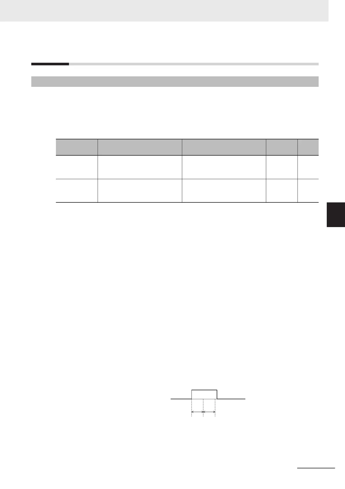
• Set the response time for each multifunction input terminal DI1 to DI7 independently. This function is
ef
fective for removing noise caused by chattering, etc. Inputs are set when the status matches twice
after checking the statues of the input terminals at each individual set response time. For example,
when 400 ms is set, up to 800 ms is required until an input is set.
Fig. 1: Example of response time matching
twice and recognition of inverter ON
Input Terminal [DI1]
Input Terminal [DI1] Response Time (H324)
5 Basic Settings
5-51
M1 Series Standard Type User's Manual (I669)
5-9 Multi-function Input
5
5-9-1 Input Terminal Functions
 Loading...