2-2-2
Terminal Blocks
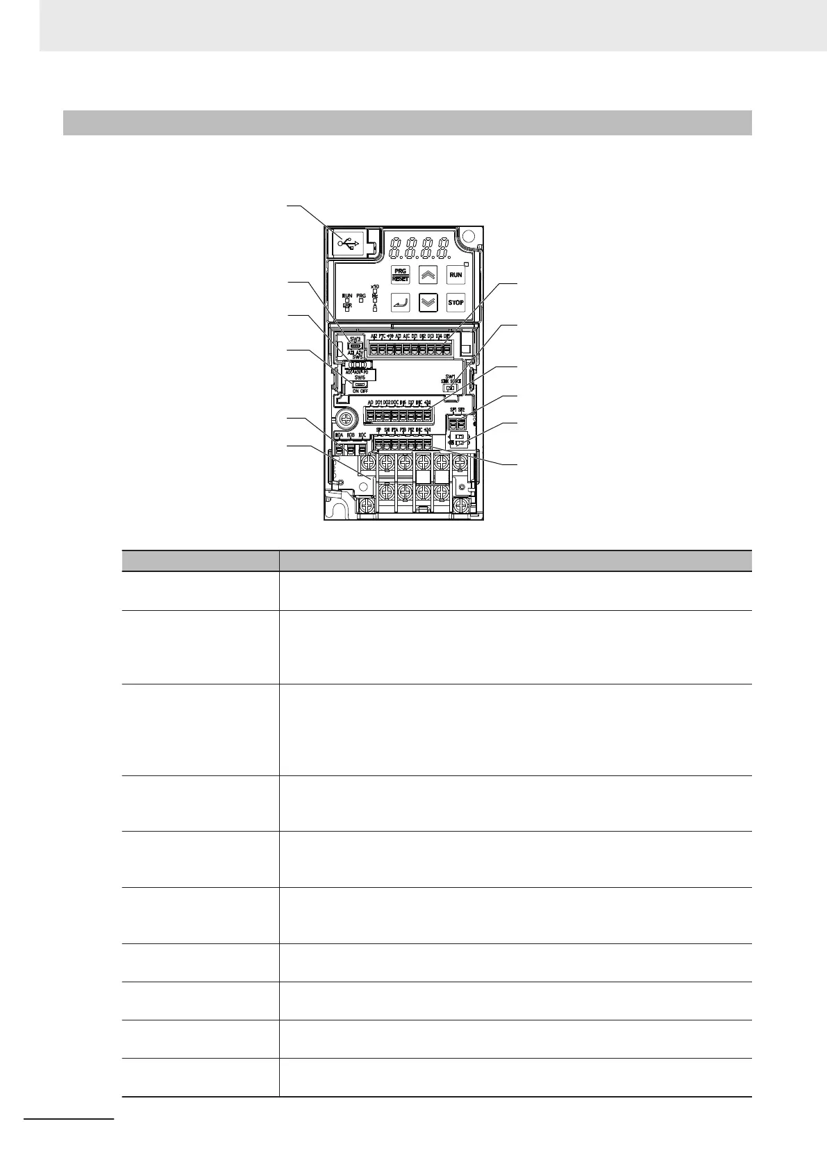
Removing the terminal block cover and each connector cover reveals terminal blocks, connectors, and
switches arranged as shown below
.
USB connector
(Micro-B)
Analog input
selector switch (SW3)
Analog input
selector switch (SW5)
Terminating resistor
selector switch (SW6)
Relay output
terminal block
Main circuit
terminal block
Control circuit terminal block A
Digital input sink/
source selector switch (SW1)
Control circuit terminal block B
Safety input terminal block
Safety function selector switch (SW9)
Control circuit terminal block C
Name Description
Digital input sink/source
selector switch (SW1)
The switch for switching which of sink or source the digital input terminals DI1 to
DI7 are to be used for
. (Factory default setting is SINK side)
Analog input selector
switch (SW3)
The switch for switching the input type of terminal AI2. (Factory default setting is AII
side)
When set to the AII side, input becomes analog current input.
When set to the AIV side, input becomes analog voltage input.
Analog output selector
switch (SW5)
The switch for switching the output type of terminal AO. (Factory default setting is
AOV side)
When set to the AOI side, output becomes analog current output.
When set to the AOV side, output becomes analog voltage output.
When set to the PO side, output becomes pulse output.
T
erminating resistor selec-
tor switch (SW6)
The switch for switching ON/OFF the RS-485 terminal on the control circuit termi-
nal block. When ON, the terminal is connected to the built-in 1
10-Ω
terminating re-
sistor. (Factory default setting is OFF side)
Safety function selector
switch (SW9)
Turn this switch OFF to use the safety function. Before you turn ON/OFF this
switch, be sure to turn off the power supply. For details, refer to
7-6 Safety Function
on page 7-69. (Factory default setting is ON side (safety function disabled))
USB connector The Micro-B type USB connector for connecting a computer.
Use this connector to connect the inverter to the Inverter/Servo support tool Sys-
mac Studio.
Control circuit terminal
block A, B, C
The terminal block for connecting various digital/analog I/O devices used for inver-
ter control.
Safety input terminal
block
The terminal block for connecting the safety input signal.
Relay output terminal
block
The SPDT contact terminal block for relay output.
Main circuit terminal block The terminal block for connecting the main power supply for the inverter, outputs to
the motor
, braking resistor, etc.
2 Design
2-8
M1 Series Standard Type User's Manual (I669)
 Loading...


