2-3
Wiring
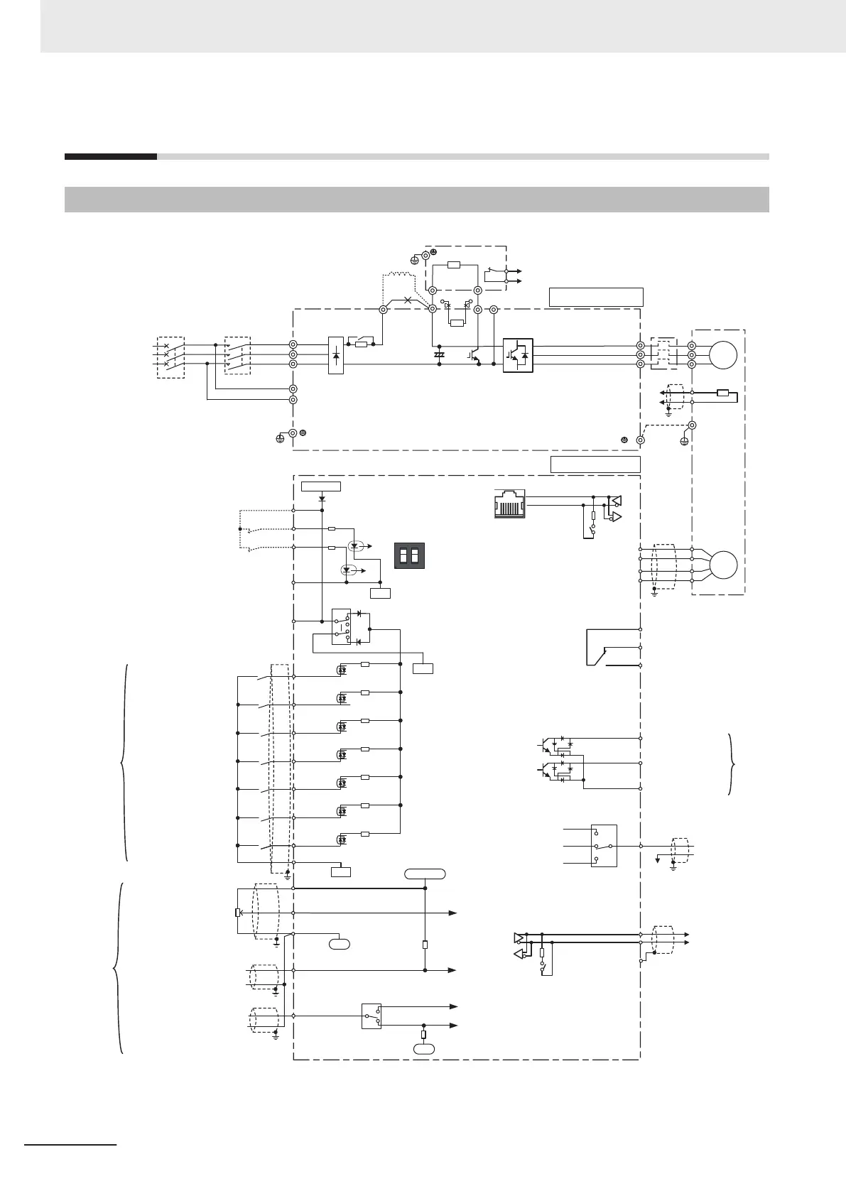
2-3-1
Standard Connection Diagram
DIC
Voltage output
(0 to 10 VDC)
+24
DI7
DI1
DI2
DI3
D
I4
DI5
DIC
SF1
SINK
SOURCE
SF2
0V
+24VDC
AO
Data send/receive
SP
SN
SW6
SW
1
SW5
AOI
AOV
AIC
AI
1
+10
+10VDC
0V
3
2
1
PTC
(+)
(-
)
Braking resistor (DBR)
DC reactor
(DCR)
DB N(-)
P(+)
P1
U
V
W
U
V
W
M
3~
L1/R
L2/S
L3/T
Magnetic
contactor
(MC)
Molded case circuit
breaker (MCCB) or
earth leakage
breaker (ELCB)
Power supply
200-V series
200 to 240 V
50/60 Hz
400-V series
380 to 480 V
50/60 Hz
G
P DB
2
1
(AIC)
(THR)
(G)
Thermistor
To [AIC]
To [PTC]
Thermal
relay
R0
T0
Control power supply
auxiliary input
G
E
Ground
terminal
Motor
Power supply for analog input
Connector for
the RJ-45
Digital Operator
SW2
RS-485
communications
terminal 1
RS-485
communications
terminal 2
(terminal block)
(SD)
Analog output /
Pulse output
AIC
Forward operation /
Stop command
Reverse operation /
Stop command
Digital input 1
Digital input 2
Digital input 3
Digital input common
Digital input 4
Digital input 5
Enable (STO)
input
Control board
Main circuit board
Ground terminal
*1
*2
*3
*4
*5
*6
*7
*8
*8
*8
*8
AI2
(+)
(-
)
DOC
ROC
ROB
ROA
Contact output
DO2
DO1
Transistor output 1
Common terminal
Transistor output 2
AIV
SW3
AII
0V
DBR
*10
*11
*11
SW9
ON
*9
+
OFF
0V
0V
*11
+24
Contact input
(seven points)
Analog input
Voltage input 0 to 10
VDC for setting
PTC input
Voltage input 0 to ±10
VDC for setting
Common for analog
input/output
Current input 4(0) to 20
mADC for setting
Current output
(4(0) to 20 mADC)
Transistor output
*11*8
*
11
PO
Pulse output
(25 to 32 pk/s)
PG
PA
PB
PZ
CM
PIA
PIB
PIZ
DIC
DI6
*1. To protect the wiring, install a molded case circuit breaker (MCCB) or earth leakage circuit breaker (ELCB)
(with overcurrent protection function) recommended for each inverter on the inverter input side (primary side).
Do not use circuit breakers whose rated current exceeds recommended values.
2 Design
2-10
M1 Series Standard Type User's Manual (I669)
 Loading...


