• Set motor (electronic thermal) protection levels using parameters F10 to F12. (For details, refer to
5-3-3 Motor Electronic Thermal Function on page 5-20
.)
• Integral solid state short circuit protection does not provide branch circuit protection. Branch circuit
protection must be provided in accordance with the National Electric Code and any additional local
codes.
The inverter does not have motor overheat protection built in.
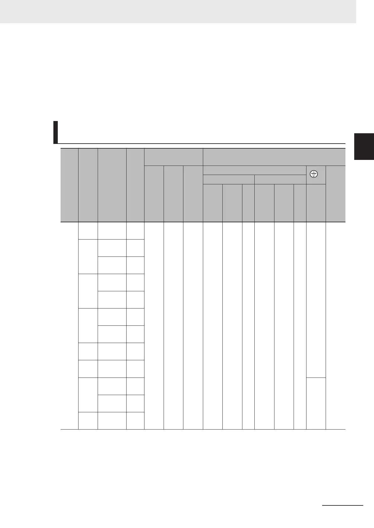
Main Circuit Terminal Block Screw Sizes, Tightening Torque and
W
ire Sizes
Power supply
system
Standard applicable
motor (kW)
Inverter Model
HHD/HD/HND/ND
modes
Tightening torque
lb-in (N・m)
Wire size AWG (mm
2
)
Main Terminal
Inverter's
grounding
Control circuit
auxiliary input
Main circuit copper wire
G
Control circuit
auxiliary input
L1/R, L2/S, L3/T U, V, W
60°C Cu Wire
75°C Cu Wire
Remarks
60°C Cu Wire
75°C Cu Wire
Remarks
Inverter's
grounding
Thre
e-
phas
e
200
V
0.1 3G3M1-
A2001
HHD 10.6
(1.2)
15.9
(1.8)
- 14
(2.1)
14
(2.1)
*3
14
(2.1)
14
(2.1)
*3
14
(2.1)
-
0.2 3G3M1-
A2001
HND
3G3M1-
A2002
HHD
0.4 3G3M1-
A2002
HND
3G3M1-
A2004
HHD
0.75 3G3M1-
A2004
HND
3G3M1-
A2007
HHD
1.1 3G3M1-
A2007
HND
1.5 3G3M1-
A2015
HHD
2.2 3G3M1-
A2015
HND 12
(3.3)
3G3M1-
A2022
HHD
3 3G3M1-
A2022
HND
2 Design
2-77
M1 Series Standard Type User's Manual (I669)
2-4 Others
2
2-4-3 UL/cUL Standards Cautions
 Loading...


