6-6
Torque Control
The 3G3M1 Series provides the torque control mode.
This section describes the torque control settings and functions.
6-6-1
Torque Control Settings
The inverter provides torque control that controls the output torque of the motor.
• This function is enabled when “5: IM Vector control without speed sensor,” “6: IM Vector control with
speed sensor” and “16: PM Vector control with speed and pole position sensor” are set in 1st Drive
Control Selection (F42)/2nd Drive Control Selection (A14).
• Torque control can be switched between enabled and disabled by the setting of parameter H18. Tor-
que control can be switched to speed control by turning “23: ATR (torque control cancel)” allocated
to Input Terminal [DI1] Function Selection to Input Terminal [DI7] Function Selection (E01 to E05,
E98, E99) to ON with the torque reference enabled.
• Select torque command input in Torque Reference Selection (H332). One of Torque Reference
(H333), analog input, and communication can be selected.
When instructing the torque command by analog input, torque becomes 0% to 200% at 0 to 10 V (4
to 20 mA).
• Because, under torque control, the speed of the inverter is determined by the balance between tor-
que and load, to prevent the inverter from going out of control, set the speed limit/acceleration level
as a percentage of the maximum frequency in d32 (for forward rotation) and d33 (for reverse rota-
tion).
• The torque command value of this torque control function takes the motor rated torque to be 100%.
• When “4: B/D (torque polarity detection)” is allocated to a multifunction output terminal, the signal for
distinguishing drive torque or braking torque is output. The OFF signal is output when the torque is
drive torque, and the ON signal is output when the torque is braking torque.
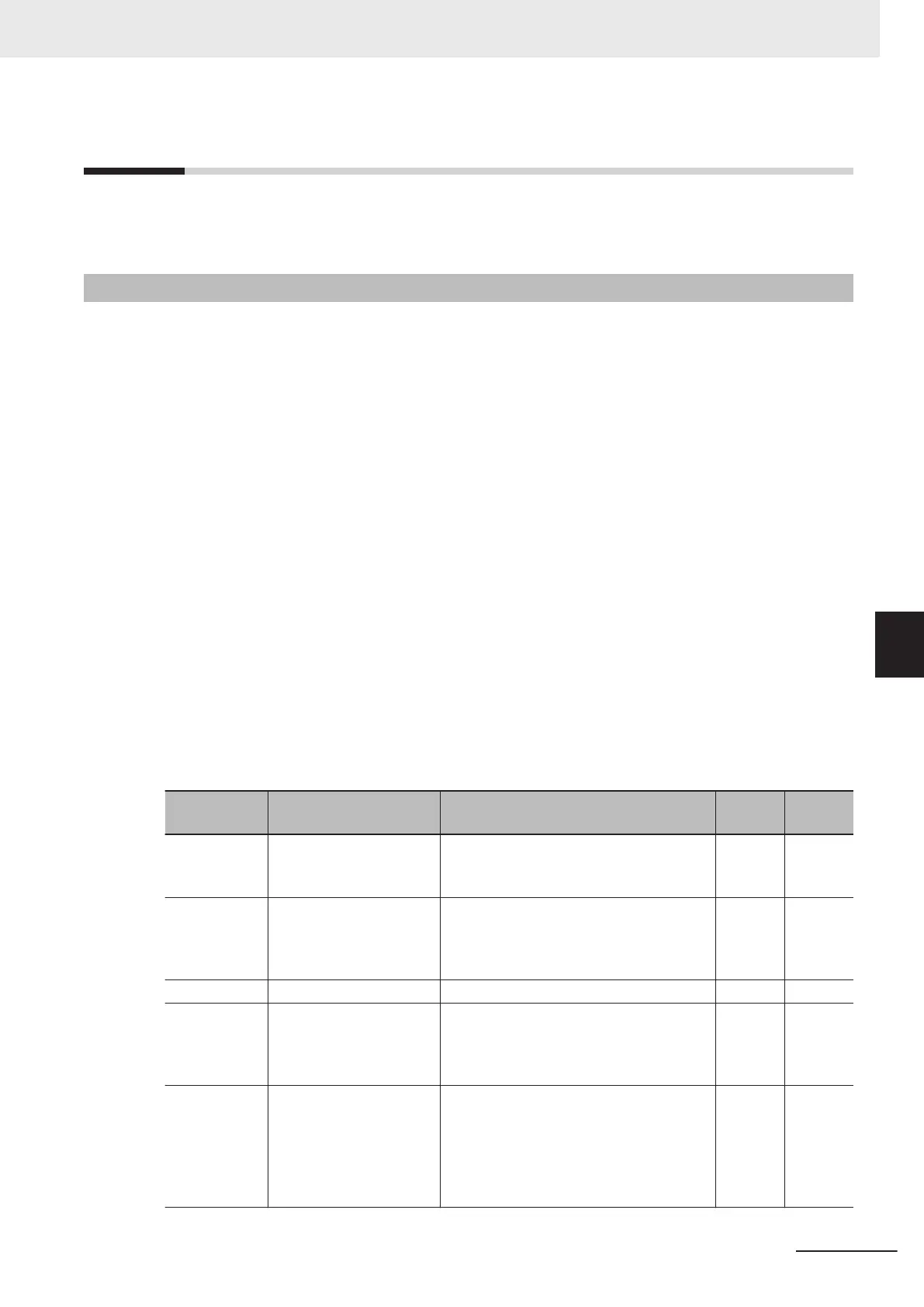
Parameter
No.
Function name Data
Default
data
Unit
H18
Torque Control Operate
Selection
0: Disable (Speed control)
2: T
orque current command input
3: Torque command input
0
-
H332
Torque Reference Selec-
tion
0: Analog input
2: Operator (H333)
4: RS-485 communication
5: Fieldbus (Reserved)
0 -
H333 Torque Reference 0 to 200 % 0 %
E01 to E05,
E98, E99
Input Terminal [DI1]
Function Selection to In-
put T
erminal [DI7] Func-
tion Selection
23: ATR (torque control cancel) -
-
E20, E21, E27
Output Terminal [DO1]
Function Selection, Out-
put Terminal [DO2] Func-
tion Selection, Output
Terminal [ROA, ROB]
Function Selection
4: B/D (torque polarity detection) -
-
6 Vector Control and Applied Functions
6-31
M1 Series Standard Type User's Manual (I669)
6-6 Torque Control
6
6-6-1 Torque Control Settings
 Loading...