• The function for switching the acceleration/deceleration time according to the output frequency when
“1: Switch frequency” is set to 1st 2-step Acceleration/ Deceleration switching Condition Selection
(E125)/2nd 2-step Acceleration/Deceleration Switching Condition Selection (E126) is disabled. Ordi-
narily, the acceleration/deceleration time is used when the output frequency is the threshold or less.
• The function for switching the acceleration/deceleration time according to the forward rotation/
reverse rotation when “2: Forward/reverse” is set to 1st 2-step Acceleration/ Deceleration switching
Condition Selection (E125)/2nd 2-step Acceleration/Deceleration Switching Condition Selection
(E126) is disabled. Ordinarily
, the acceleration/deceleration time on the forward rotation side is
used.
Deceleration Time for Forced Stop (H56) is selected for the acceleration/deceleration time in the fol-
lowing cases:
• When the RUN command (FWD, REV) is shut off and deceleration is performed during position con-
trol
• When an emergency stop is performed by detection of an overtravel (OT) or input of the “STOP”
signal
6-7-5
Positioning Data
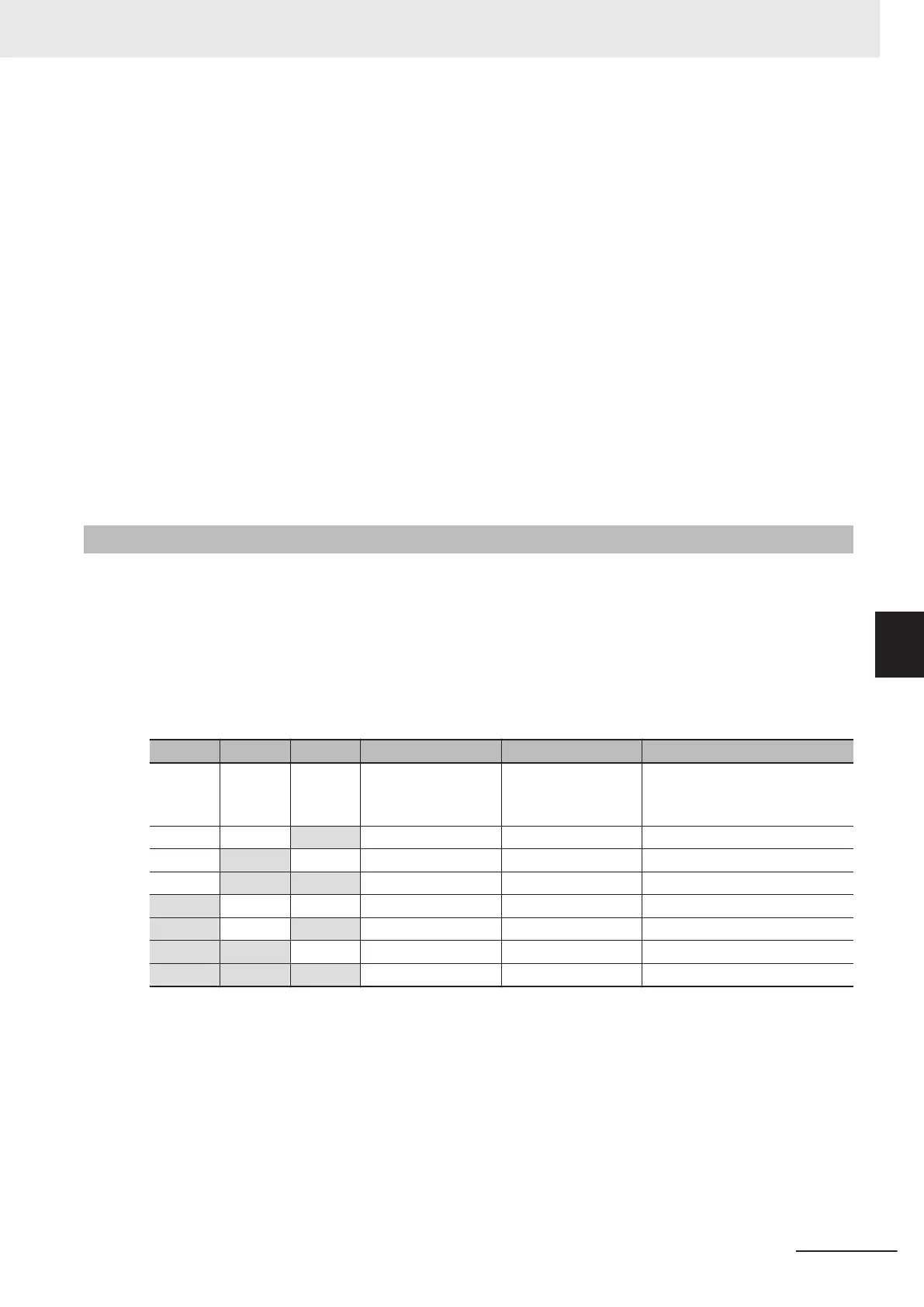
Positioning data for up to eight points can be set in user value units. Positioning data is selected in
combinations of position command selection signals “CP1” “CP2” and “CP3” via digital input. T
o pre-
vent chattering at contacts, selection is switched when a position command selection signal has not
changed state until the Position Data Determination Time (d238) elapses. Positioning data can be
changed during position control. T
o reflect a newly changed position, turn the position change com-
mand “POS-SET” ON. When positioning data is changed during a stop, operation by position change
command “POS-SET” is not required.
“CP3” “CP2” “CP1” Parameter Data Range (user value unit)
OFF OFF OFF d244, d245 Positioning data 1
±268435455
(F000 0001 hex to 0FFF FFFF
hex)
OFF OFF ON d246, d247 Positioning data 2 ±268435455
OFF ON OFF d248, d249 Positioning data 3 ±268435455
OFF ON ON d250, d251 Positioning data 4 ±268435455
ON OFF OFF d252 d253 Positioning data 5 ±268435455
ON OFF ON d254, d255 Positioning data 6 ±268435455
ON ON OFF d256, d257 Positioning data 7 ±268435455
ON ON ON d258, d259 Positioning data 8 ±268435455
6 Vector Control and Applied Functions
6-41
M1 Series Standard Type User's Manual (I669)
6-7 Position Control
6
6-7-5 Positioning Data
 Loading...