7-1
Status Monitors
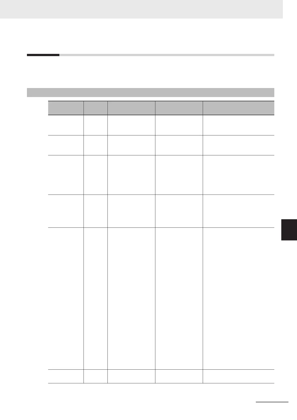
This section describes the output frequency, fault monitor during trip, and other monitor functions of
the inverter.
7-1-1
Operation Monitor
Item No.
Parame-
ter No.
Item Range Display item
3_00 W03
Output Frequency
Monitor before Slip
Compensation
0.00 to 590.00 [Hz]
Output frequency 1 (before slip
compensation) is displayed in in-
crements of 0.01 Hz.
3_01 W115
Output Frequency Af-
ter Slip Compensa-
tion
0.00 to 590.00 [Hz]
Output frequency 2 (after slip
compensation) is displayed in in-
crements of 0.01 Hz.
3_02 W05
Output Current Moni-
tor
0.00 to 655.3 [A]
Output current effective value is
displayed in increments of 0.01
A.
A current value of 100 A or higher
is displayed in increments of 0.1
A.
3_03 W06
Output Voltage Moni-
tor
0.0 to 999.0 [V]
The output voltage command val-
ue is displayed in increments of
0.1 V
.
However, the display value
changes in increments of 1.0 V
.
3_04 W07
Output Torque Moni-
tor
-400 to 400 [%]
The torque calculated value, tor-
que command value and torque
current command value are dis-
played in increments of 1%.
• Rated motor torque ratio of tor-
que calculated value in the
case of V/f control and dynam-
ic torque vector control
• Speed control mode of vector
control: Rated motor torque ra-
tio of speed control output (af-
ter torque bias)
• When the torque command is
used in the torque control
mode of vector control: Rated
motor torque ratio of torque
command value
• When the torque current com-
mand is used in the torque
control mode of vector control:
Rated motor current ratio of
torque current command value
3_05 W02
Frequency Reference
Monitor
0.00 to 590.00 [Hz]
Displays the set frequency in in-
crements of 0.01 Hz and 100 Hz.
7 Other Functions
7-3
M1 Series Standard Type User's Manual (I669)
7-1 Status Monitors
7
7-1-1 Operation Monitor
 Loading...