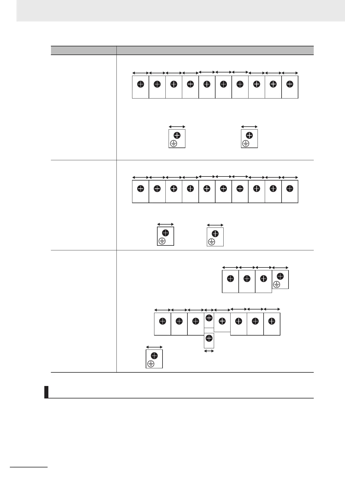
Applicable model Terminal arrangement
3G3M1-AB037
3G3M1-A2055/A2075
3G3M1-A4055/A4075
P1 P(+) N(-)
DB U V
W
G G
L1/R
16.2
(0.64)
16.2
(0.64)
16.2
(0.64)
16.2
(0.64)
16.2
(0.64)
16.2
(0.64)
L3/TL2/S
18.5
(0.73)
18.5
(0.73)
16.2
(0.64)
16.2
(0.64)
16.2
(0.64)
16.2
(0.64)
(For single-phase class, connect L1/L to L1/R and L2/N to L3/T.)
3G3M1-A2110/A2150
3G3M1-A4110/A4150
P1 P(+) N(-)
DB U V
W
G
G
L1/R
13
(0.51)
13
(0.51)
13
(0.51)
13
(0.51)
13
(0.51)
13
(0.51)
L3/TL2/S
12.8
(0.50)
12.8
(0.50)
13
(0.51)
13
(0.51)
13
(0.51)
13
(0.51)
3G3M1-A2185
3G3M1-A4185/A4220
P1 P(+) N(-)
DB
U V
W
G
G
L1/R
22
(0.87)
22
(0.87)
22
(0.87)
22
(0.87)
22
(0.87)
22
(0.87)
L3/TL2/S
16.5 (0.65)
16.5
(0.65)
16.5
(0.65)
22
(0.87)
22
(0.87)
22
(0.87)
R0
6.6
(0.26)
T0
6.6
(0.26)
Recommended Cable Size, Wiring Device, and Crimp Terminal
For inverter wiring, crimp terminal, and terminal screw tightening torque, refer to the table below.
• Each table shows an example of connecting the standard three-phase motor with four poles to an
inverter.
•
For the molded case circuit breaker (MCCB), select an appropriate product in consideration of the
breaking capacity.
2 Design
2-18
M1 Series Standard Type User's Manual (I669)
 Loading...


