88
"A" Group: Standard Functions Section 3-5
Note The setting A073 for the integrator is the integrator's time constant Ti, not the
gain. The integrator gain Ki = 1/Ti. When you set
A073 = 0, the integrator is dis-
abled.
In standard operation, the inverter uses a reference source selected by
parameter
A001 for the output frequency, which may be a fixed value (F001), a
variable set by the front panel potentiometer, or value from an analog input
(voltage or current). To enable PID operation, set
A071=01. This causes the
inverter to calculate the target freq, or setpoint.
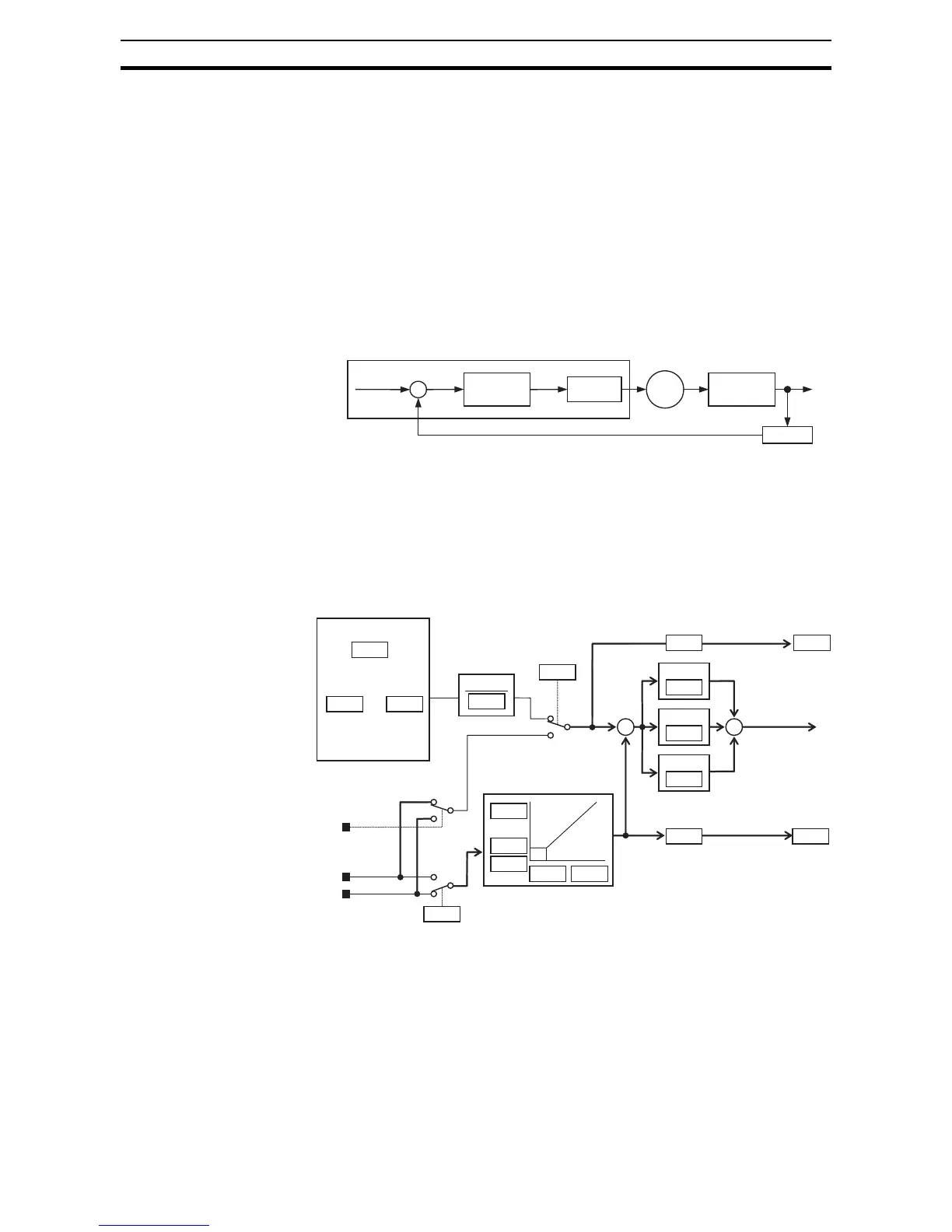
A calculated target frequency can have a lot of advantages. It lets the inverter
adjust the motor speed to optimize some other process of interest, potentially
saving energy as well. Refer to the figure below. The motor acts upon the
external process. To control that external process, the inverter must monitor
the process variable. This requires wiring a sensor to either the analog input
terminal [O] (voltage) or terminal [OI] (current).
When enabled, the PID loop calculates the ideal output frequency to minimize
the loop error. This means we no longer command the inverter to run at a par-
ticular frequency, but we specify the ideal value for the process variable. That
ideal value is called the setpoint, and is specified in the units of the external
process variable. For a pump application it may be gallons/minute, or it could
be air velocity or temperature for an HVAC unit. Parameter A075 is a scale fac-
tor that relates the external process variable units to motor frequency. The fig-
ure below is a more detailed diagram of the function.
The PID Disable function temporarily suspends PID loop execution via an
intelligent input terminal. It overrides the parameter
A071 (PID Enable) to stop
PID execution and return to normal motor frequency output characteristics.
The use of PID Disable on an intelligent input terminal is optional. Of course,
any use of the PID loop control requires setting PID Enable function
A071=01.
The PID Clear function forces the PID loop integrator sum = 0. So, when you
turn ON an intelligent input configured as [PIDC], the integrator sum is reset to
zero. This is useful when switching from manual control to PID loop control
and the motor is stopped.
Setpoint
SP
+
PID
Calculation
Error Freq.
Inverter Motor
External
Process
Sensor
Process Variable (PV)
PV
F001
A020 A035
A075
1
A001
+
A072
P gain
A073
I gain
A074
D gain
+
A075 F001
SP
A101
A102
A105
A103 A104
V/I select
[AT]
[O]
Voltage
[OI]
Current
A076
PID V/I input select
d004A075
Monitor
Standard setting
Setpoint
(Target)
Process variable (Feedback)
Analog input scaling (OI)
Multi-speed
setting
to
POT meter on
ext. panel
Scale factor
Reciprocal
Frequency
source select
Frequency
setting
Scale factor
Scale factor
 Loading...


