172
Intelligent Terminal Listing Section 4-4
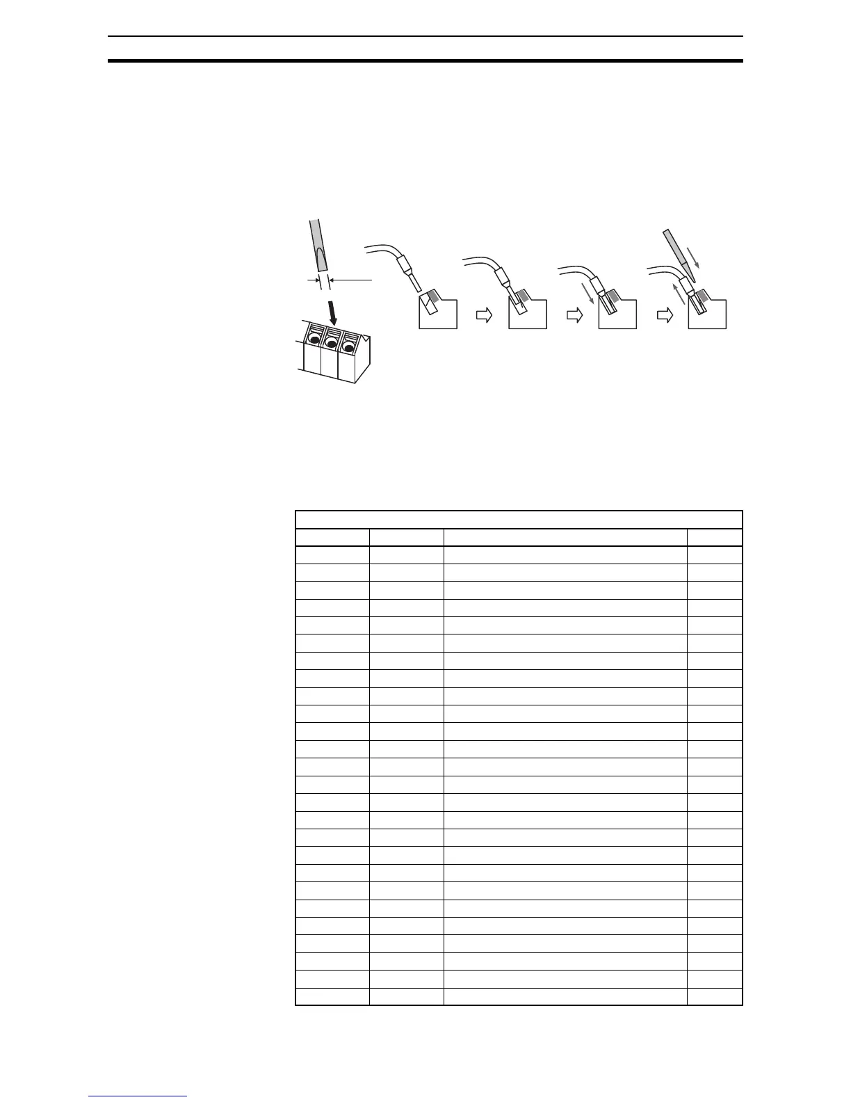
4-3-5 How to connect?
1. Push down the cable in the inputan orange actuating lever by a slotted
screwdriver (width 2.5 mm max.).
2. Plug in the conductor making pressure.
3. To remove the wire push down the orange actuating lever by a slotted
screwdriver (width 2.5 mm max.) Then pull out the cable while pressing the
screwdriver.
4-4 Intelligent Terminal Listing
4-4-1 Intelligent Inputs
Use the following table to locate pages for intelligent input material in this
chapter.
Input Function Summary Table
Symbol Code Function Name Page
FW 00 Forward Run/Stop 179
RV 01 Reverse Run/Stop 179
CF1 02 Multi-speed Select, Bit 0 (LSB) 74
CF2 03 Multi-speed Select, Bit 1 74
CF3 04 Multi-speed Select, Bit 2 74
CF4 05 Multi-speed Select, Bit 3 (MSB) 74
JG 06 Jogging 77
DB 07 External DC braking 83
SET 08 Set (select) 2nd Motor Data 180
2CH 09 2-stage Acceleration and Deceleration 93
FRS 11 Free-run Stop 181
EXT 12 External Trip 182
USP 13 Unattended Start Protection 182
CS 14 Commercial power source switchover 183
SFT 15 Software Lock 106
AT 16 Analog Input Voltage/Current Select 71
RS 18 Reset Inverter 184
PTC 19 PTC thermistor Thermal Protection 185
STA 20 Start (3-wire interface) 186
STP 21 Stop (3-wire interface) 186
F/R 22 FWD, REV (3-wire interface) 186
PID 23 PID Disable 87
PIDC 24 PID Reset 87
UP 27 Remote Control UP Function 187
DWN 28 Remote Control Down Function 187
UDC 29 Remote Control Data Clearing 187
 Loading...


