EasyManua.ls Logo

Omron MX2 User Manual

Omron MX2
356 pages
To Next Page IconTo Next Page
To Previous Page IconTo Previous Page
Page #140 background imageLoading...
Page #140 background image
118
"B" Group: Fine Tuning Functions Section 3-6
3-6-15 Window Comparator, Analog disconnection
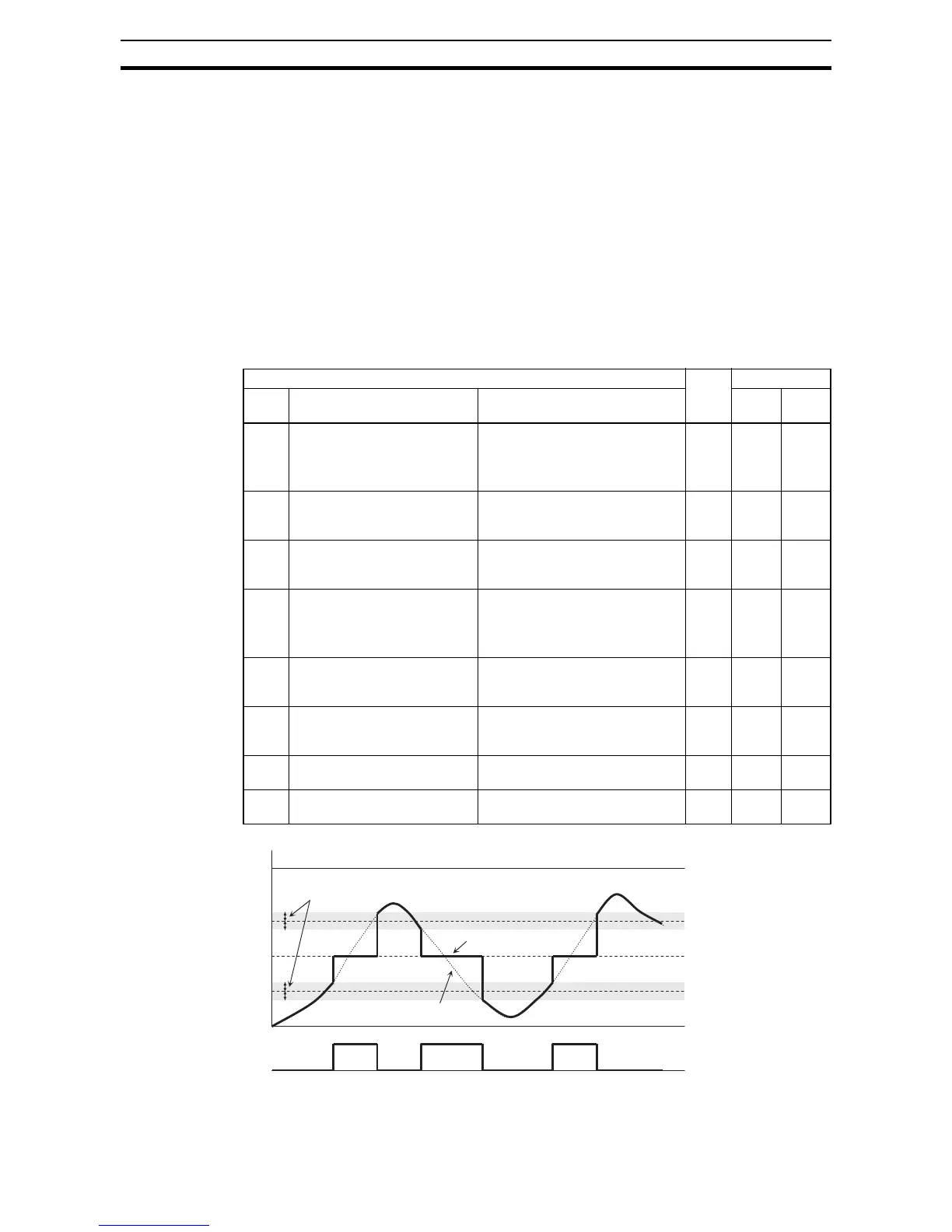
The window comparator function outputs signals when the values of analog
inputs O and OI are within the maximum and minimum limits specified for the
window comparator. You can monitor analog inputs with reference to arbitrary
levels (to find input terminal disconnection and other errors).
You can specify a hysteresis width for the maximum-limit and minimum-limit
levels of the window comparator. You can also specify limit levels and a hys-
teresis width individually for analog inputs O and OI.
You can fix the analog input data to be applied to an arbitrary value when
WCO or WCOI is output. For this purpose, specify a desired value as the
operation level at O/OI disconnection (b070/b071/b072). When "no" is speci-
fied, the analog input data is reflected as input.
Output values of Odc and OIDc are the same as those of WCO and WCOI,
respectively.
"B" Function Run
Mode
Edit
Defaults
Func.
Code
Name Description EU Units
B060 Maximum-limit level of window
comparator (O)
Set range, {Min.-limit level (b061)
+ hysteresis width (b062)x2} to
100%
(Minimum of 0%)
8 100 %
B061 Minimum-limit level of window
comparator (O)
Set range, 0 to {Max.-limit level
(b060) - hysteresis width
(b062)x2}% (Maximum of 0%)
9 0%
B062 Hysteresis width of window
comparator (O)
Set range, 0 to {Max.-limit level
(b060) - Min.-limit level (b061)}/2%
(Maximum of 10%)
9 0%
B063 Maximum-limit level of window
comparator (OI)
Set range, {Min.-limit level (b064
+ hysteresis width (b065)x2} to
100%
(Minimum of 0%)
9 100 %
B064 Minimum-limit level of window
comparator (OI)
Set range, 0 to {Max.-limit level
(b063) - hysteresis width
(b065)x2}% (Maximum of 0%)
9 0%
b065 Hysteresis width of window
comparator (OI)
Set range, 0 to {Max.-limit level
(b063) - Min.-limit level (b064)}/2%
(Maximum of 10%)
9 0%
b070 Operation level at O
disconnection
Set range, 0 to 100%, or "no"
(ignore)
8 no -
b071 Operation level at OI
disconnection
Set range, 0 to 100%, or "no"
(ignore)
8 no -
Hysteresis width
(b062, b065, b068)
Analog input data
Applied analog data
O or OI
Max.(100%)
0%
WCO/WCOI
Odc/OIDc
Max.-limit level of window
comparator ( b061/b064)
Min.-limit level of window
comparator ( b060/b063)
Analog operation level at
disconnection ( b070/b071)
ON ON ON

Table of Contents

Other manuals for Omron MX2

Question and Answer IconNeed help?

Do you have a question about the Omron MX2 and is the answer not in the manual?

Omron MX2 Specifications

General IconGeneral
ModelMX2
CategoryInverter
Enclosure RatingIP20
Control MethodV/f control, Sensorless vector control
Frequency Range0.1 to 400 Hz
ProtectionOvercurrent, Overvoltage, Undervoltage, Overheat, Short circuit
CommunicationModbus RTU
Ambient Temperature-10 to 50 °C (without freezing or condensation)
Overload Capacity150% for 60 seconds
Cooling MethodFan Cooled
Humidity5 to 95% RH (without condensation)
AltitudeUp to 1000m without derating
Voltage200-240 VAC, 380-480 VAC
Braking UnitBuilt-in (for certain models), Optional External

Summary

MX2

Warranty and Limitations of Liability

WARRANTY

Outlines OMRON's one-year warranty against defects in materials and workmanship.

SECTION 1 GETTING STARTED

SECTION 2 Inverter Mounting and Installation

Step-by-Step Basic Installation

Provides a detailed, step-by-step guide for installing the inverter, including precautions.

Powerup Test

Guides the user through the initial powerup test to verify correct wiring and general compatibility.

Using the Front Panel Keypad

Explains the layout and function of the inverter's keypad for programming and monitoring.

SECTION 3 Configuring Drive Parameters

"C" Group: Intelligent Terminal Functions

Details configuration for logic (discrete) and analog outputs and inputs.

"H" Group: Motor Constants Functions

Details parameters for configuring motor characteristics and performing auto-tuning for optimal performance.

SECTION 4 Operations and Monitoring

Caution Messages for Operating Procedures

Lists critical caution messages that must be read before operating the inverter.

Connecting to PLCs and Other Devices

Explains how to interface the inverter with external devices like PLCs for control.

Safe Stop Function

Explains the Gate Suppress function for safe stop according to EN60204-1.

SECTION 5 Inverter System Accessories

SECTION 6 Troubleshooting and Maintenance

Troubleshooting

Provides safety messages, general precautions, inspection items, and troubleshooting tips for common issues.

Restoring Factory Default Settings

Guides users on resetting inverter parameters to their original factory default values.

Appendix B ModBus Network Communications

Appendix D CE-EMC Installation Guidelines

CE-EMC Installation Guidelines

Provides guidelines for installing the inverter to meet EMC directive requirements in the EU.

Appendix E Safety (ISO 13849-1)

Related product manuals