47
Using the Front Panel Keypad Section 2-5
2-5 Using the Front Panel Keypad
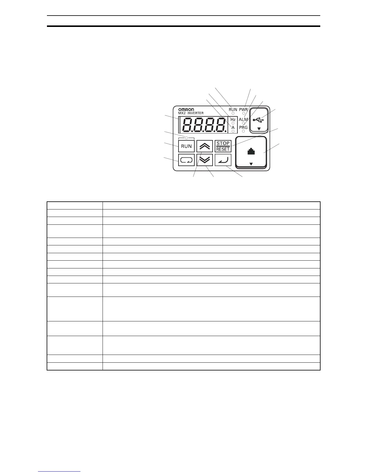
Please take a moment to familiarize yourself with the keypad layout shown in
the figure below. The display is used in programming the inverter's parame-
ters, as well as monitoring specific parameter values during operation.
Items Contents
(1) POWER LED Turns ON (Green) while the inverter is powered up.
(2) ALARM LED Turns ON (Red) when the inverter trips.
(3) Program LED · Turns ON (Green) when the display shows changeable parameter.
· Blinks when there is a mismatch in setting.
(4) RUN LED Turns ON (Green) when the inverter is driving the motor.
(5) Monitor LED [Hz] Turns ON (Green) when the displayed data is frequency related.
(6) Monitor LED [A] Turns ON (Green) when the displayed data is current related.
(7) Run command LED Turns ON (Green) when a Run command is set to the operator. (Run key is effective.)
(8) 7-seg LED Shows each parameter, monitors etc.
(9) Run key Makes inverter run.
(10) Stop/reset key · Makes inverter decelerates to a stop.
· Reset the inverter when it is in trip situation
(11) CYCLE key · Go to the top of next function group, when a function mode is shown
· Cancel the setting and return to the function code, when a data is shown
· Moves the cursor to a digit left, when it is in digit-to-digit setting mode
· Pressing for 1 second leads to display data of d001, regardless of current display.
(12) Up key
(13) Down key
· Increase or decrease the data.
· Pressing the both keys at the same time gives you the digit-to-digit edit.
(14) SET key · Go to the data display mode when a function code is shown
· Stores the data and go back to show the function code, when data is shown.
· Moves the cursor to a digit right, when it is in digit-to-digit display mode
(15) USB connector Connect USB connector (mini-B) for using PC communication
(16) RJ45 connector Connect RJ45 jack for remote operator