26
Basic System Description Section 2-2
2-2 Basic System Description
A motor control system will obviously include a motor and inverter, as well as
a circuit breaker or fuses for safety. If you are connecting a motor to the
inverter on a test bench just to get started, that's all you may need for now. But
a system can also have a variety of additional components. Some can be for
noise suppression, while others may enhance the inverter's braking perfor-
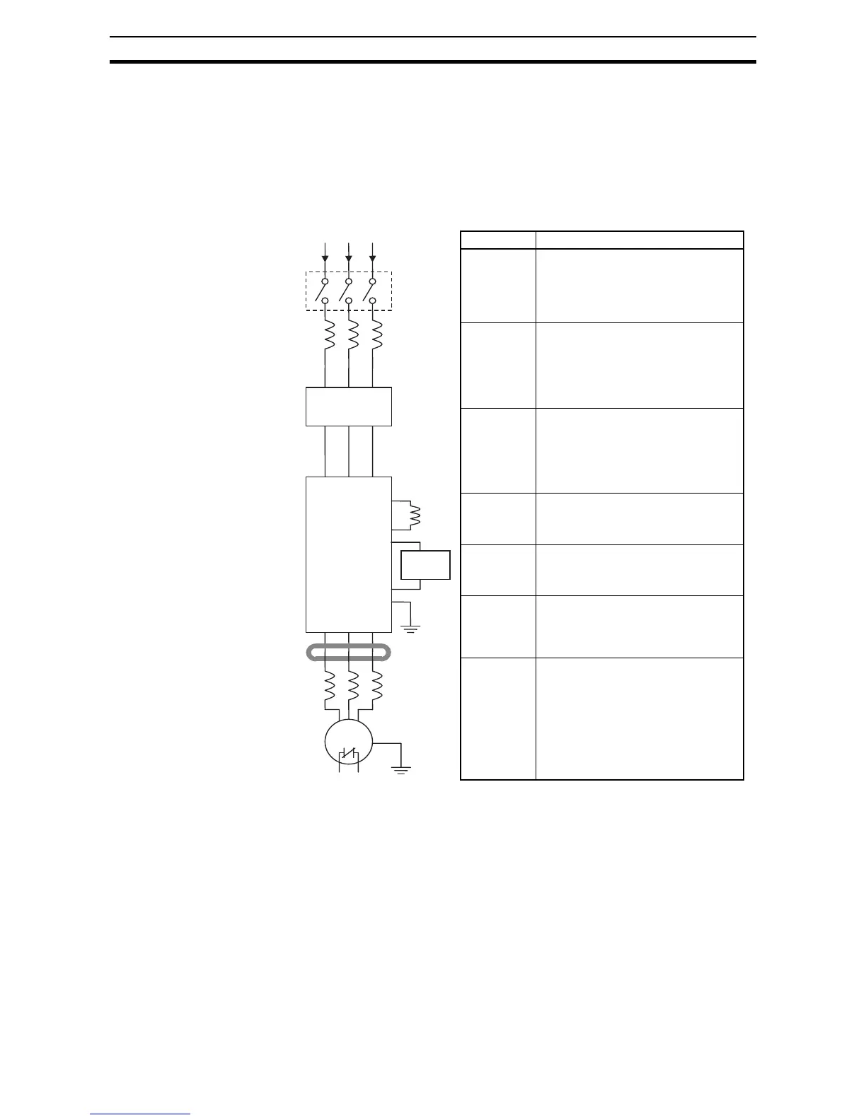
mance. The figure and table below show a system with all the optional com-
ponents you might need in your finished application.
Note Note that some components are required for regulatory agency compliance
(see SECTION 5 Inverter System Accessories and Appendix D CE-EMC
Installation Guidelines).
Breaker,
MCCB or
GFI
From power supply
Motor
Thermal
switch
L1 L2 L3
T1 T2 T3
Inverter
+1
+
+
GND
EMI filter
DC link
choke
RF noise
filter choke
AC reactor
(Input choke)
AC reactor
(Output choke)
Braking
Resistor
RB
Name Function
Breaker /
disconnect
A molded-case circuit breaker (MCCB),
ground fault interrupter (GFI), or a fused
disconnect device. NOTE: The installer
must refer to the local country norms of
application to ensure safety and compli-
ance.
Input-side
AC Reactor
This is useful in reducing low frequency
harmonics distortion induced on the
power supply lines and as consequence
improve the power factor. WARNING:
Some applications must use an input-
side AC Reactor to prevent inverter
damage. See Warning on next page.
EMC filter
(for CE appli-
cations, see
Appendix D)
Reduces the conducted high frequency
noise on the power supply wiring
between the inverter and the power dis-
tribution system. Connect to the inverter
primary (input) side.
DC link
choke
Reduce harmonics generated by the
inverter motor driving section, by
smoothing the current demand of the
capacitors.
Braking
Resistor
Used to disipate regenerative energy
from the motor that is accumulated into
the DC bus charging the capacitors and
increasing the voltage.
Radio noise
output filter
Electrical noise interference may occur
on nearby equipment such as a radio
receiver. This magnetic choke filter
helps reduce very high frequency radi-
ated noise (can also be used on input).
Output-side
AC Reactor
This reactor in its standard type (only L
inductor), prevents the high voltage
ringing of PWM modulation to reach the
motor, compensating for the capacity of
the motor cables, specially with long
lengths.
For more effective (and expensive)
options, like sinus filter (targetting net-
work-like waveforms) or dV/dt filters,
please check with your dealer.
 Loading...


