210
Using Intelligent Output Terminals Section 4-6
4-6-14 Electronic Thermal Warning Signal Output
You can configure this function so that the inverter outputs a warning signal
before the electronic thermal protection operates against motor overheat. You
can also set the threshold level to output a warning signal with the electronic
thermal warning level setting (
C061).
To output the warning signal, assign function "
13 (THM)" to one of the intelli-
gent output terminals [11] to [12], or to the relay output terminal.
4-6-15 External Brake Related Output Signals
These signals are used with brake control function.
To output the warning signals, assign function "
19 (BRK)" and "20 (BER)" to
the intelligent output terminals [11] and [12], or to the relay output terminal.
Refer to SECTION 3 Configuring Drive Parameters on page 59 detailed
explanation of the brake control function.
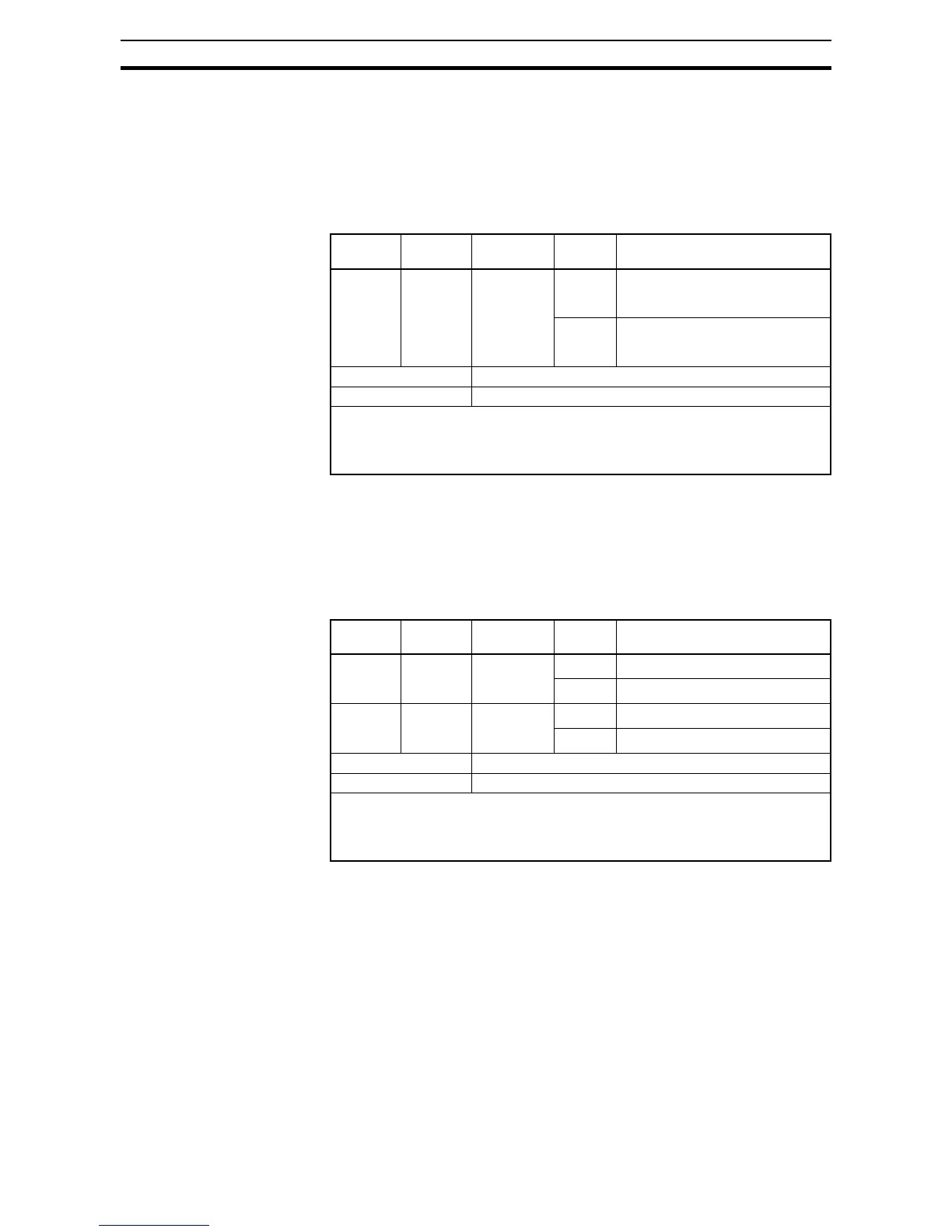
Option
Code
Terminal
Symbol
Function
Name
State Description
13 THM Thermal
warning sig-
nal output
ON Accumulated thermal level exceeds
the electronic thermal warning level
(C061)
OFF Accumulated thermal level does
not exceed the electronic thermal
warning level (C061)
Valid for inputs: 11, 12, AL0 - AL2
Required settings: C061
Notes:
• The example circuit for terminal [11] drives a relay coil. Note the use of a diode to
prevent the negative-going turn-off spike generated by the coil from damaging the
inverter's output transistor.
Option
Code
Terminal
Symbol
Function
Name
State Description
19 BRK Brake
release
signal
ON Brake is ready to be released
OFF Brake is not ready to be released
20 BER Brake
error
signal
ON Brake error has occurred
OFF Brake is working properly
Valid for inputs: 11, 12, AL0 - AL2
Required settings: b120~b127
Notes:
• The example circuit for terminal [11] drives a relay coil. Note the use of a diode to
prevent the negative-going turn-off spike generated by the coil from damaging the
inverter's output transistor.
 Loading...


