208
Using Intelligent Output Terminals Section 4-6
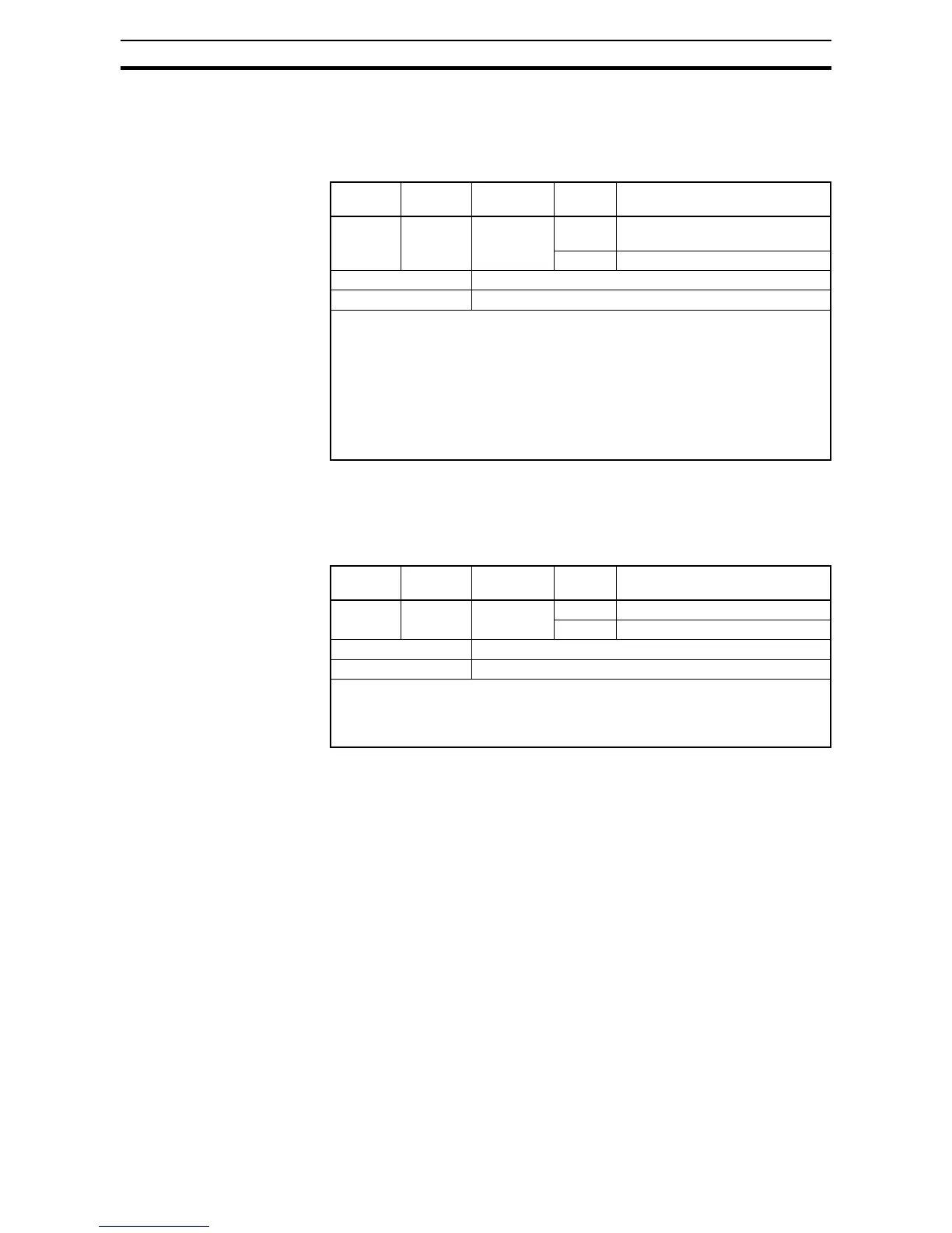
4-6-10 Over Torque Signal
The inverter outputs the over torque signal when it detects that the estimated
motor output torque exceeds the specified level.
To enable this function, assign "
07 (OTQ)" to an intelligent output terminal.
4-6-11 Undervoltage Signal
The inverter outputs the undervoltage signal when it detects that the inverter
is in undervoltage situation.
To enable this function, assign "
09 (UV)" to an intelligent output terminal.
Option
Code
Terminal
Symbol
Function
Name
State Description
07 OTQ Over torque
signal
ON when the estimated output torque >
C055~C058
OFF when no over torque is detected
Valid for inputs: 11, 12, AL0 - AL2
Required settings: A044=03 or 04, C055~C058
Notes:
• This function is effective only when the V/F characteristic curve selection A044 is
set to "03 (SLV mode)". With any other V/F characteristic curve selection, the out-
put of the OTQ signal is unpredictable.
• When using the inverter for a lift, use the OTQ signal as the trigger to stop braking.
Use the frequency arrival signal as the trigger to start braking.
• The example circuit for terminal [11] drives a relay coil. Note the use of a diode to
prevent the negative-going turn-off spike generated by the coil from damaging the
inverter's output transistor.
Option
Code
Terminal
Symbol
Function
Name
State Description
09 UV Undervolt-
age signal
ON Inverter is in undervoltage
OFF Inverter is in normal condition
Valid for inputs: 11, 12, AL0 - AL2
Required settings:
Notes:
• The example circuit for terminal [11] drives a relay coil. Note the use of a diode to
prevent the negative-going turn-off spike generated by the coil from damaging the
inverter's output transistor.
 Loading...


