152
"H" Group: Motor Constants Functions Section 3-8
10. When performing the auto-tuning with one lower size of motor, enable the
overload restriction function, and set the overload restriction level to 150%
of the rated current of the motor.
11. When deceleration over-voltage suppress integral time (b134) is small,
auto-tuning may result in over-voltage trip. In this case, increase b134 and
retry the auto-tuning.
12. To execute auto-tuning, be sure to set the output frequency (F001) larger
than starting frequency (b082) regardless with or without rotation.
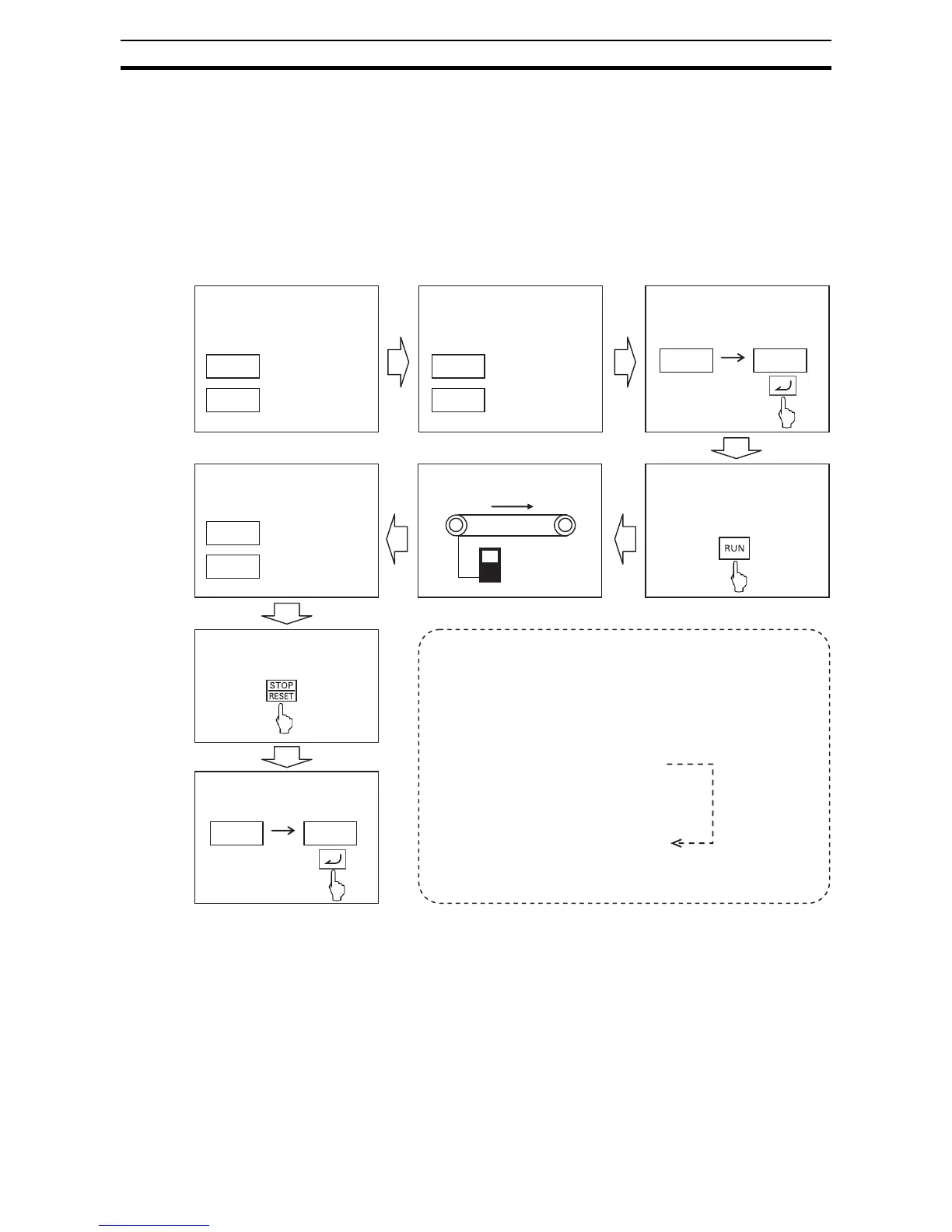
Off-line auto-tuning procedure (with motor rotation)
Note 1 When no-rotation setting (H001=01), (4) and (5) are skipped.
Note 2 After auto-tuning is completed, be sure to set 02 in H002/H202, otherwise
measured data is not effective.
Note 3 Speed "X" of above (5) depends on accel/deceleration time.
(T: Larger time of accel or deceleration time)
0 < T < 50 [s] : X=40%
50 ≤ T < 100 [s] : X=20%
100 ≤ T [s] : X=10%
Note 4 If auto-tuning is failed, try to execute again.
H003
Motor size
Motor poles
Base freq.
AVR voltage
H004
A003
A082
H001 02
___o
Completed
Failed
___9
H002 02
(1) 1st AC excitation (no rotation)
(2) 2nd AC excitation (no rotation)
(3) 1st DC excitation (no rotation )
(4) V/f operation (80% of base freq.)
(5) SLV operation (X % of base freq.)
(6) 2nd DC excitation (no rotation)
(7) Displays the result.
Step 1: Set motor size and
motor poles
Step 5: Clear display by
STOP key
Step 6: Activate motor
constant by H002
Step 2:Set base freq.
and
AVR voltage
Result is displayed
(Note 1)
Auto-tuning starts
When RUN cmd. is given, the motor runs according to
following steps.
Step 3: Enab le auto-tuning
Step 4: Start the inverter
according to RUN
cmd source
 Loading...


