224
Analog Input Operation Section 4-7
Current Input – The current input circuit
uses terminals [OI] and [L]. The current
comes from a sourcing type transmitter; a
sinking type will not work! This means the
current must flow into terminal [OI], and ter-
minal [L] is the return back to the transmitter.
The input impedance from [OI] to [L] is
100 Ohms. Attach the cable shield wire only
to terminal [L] on the inverter.
See I/O specs on
page 169.
The following table shows the available analog input settings. Parameter
A005
and the input terminal [AT] determine the External Frequency Command input
terminals that are available, and how they function. The analog inputs [O] and
[OI] use terminal [L] as the reference (signal return).
4-7-1 Other Analog Input-related topics:
• "Analog Input Settings"
• "Additional Analog Input Settings"
• "Analog Signal Calibration Settings"
• "Analog Input Current/Voltage Select"
• "ADD Frequency Enable"
• "Analog Input Disconnect Detect"
4-7-2 Pulse Train Input Operation
The MX2 inverter is capable of accepting pulse train input signals, that are
used for frequency command, process variable (feedback) for PID control,
and simple positioning. The dedicated terminal is called "EA" and "EB". Termi-
nal "EA" is a dedicated terminal, and the terminal "EB" is an intelligent termi-
nal, that has to be changed by a parameter setting.
A005 [AT] Input Analog Input Configuration
00 ON [O]
OFF [OI]
02 ON [O]
OFF Integrated POT on external panel
03 ON [OI]
OFF Integrated POT on external panel
4 to 19.6 mA DC,
4 to 20 mA nominal
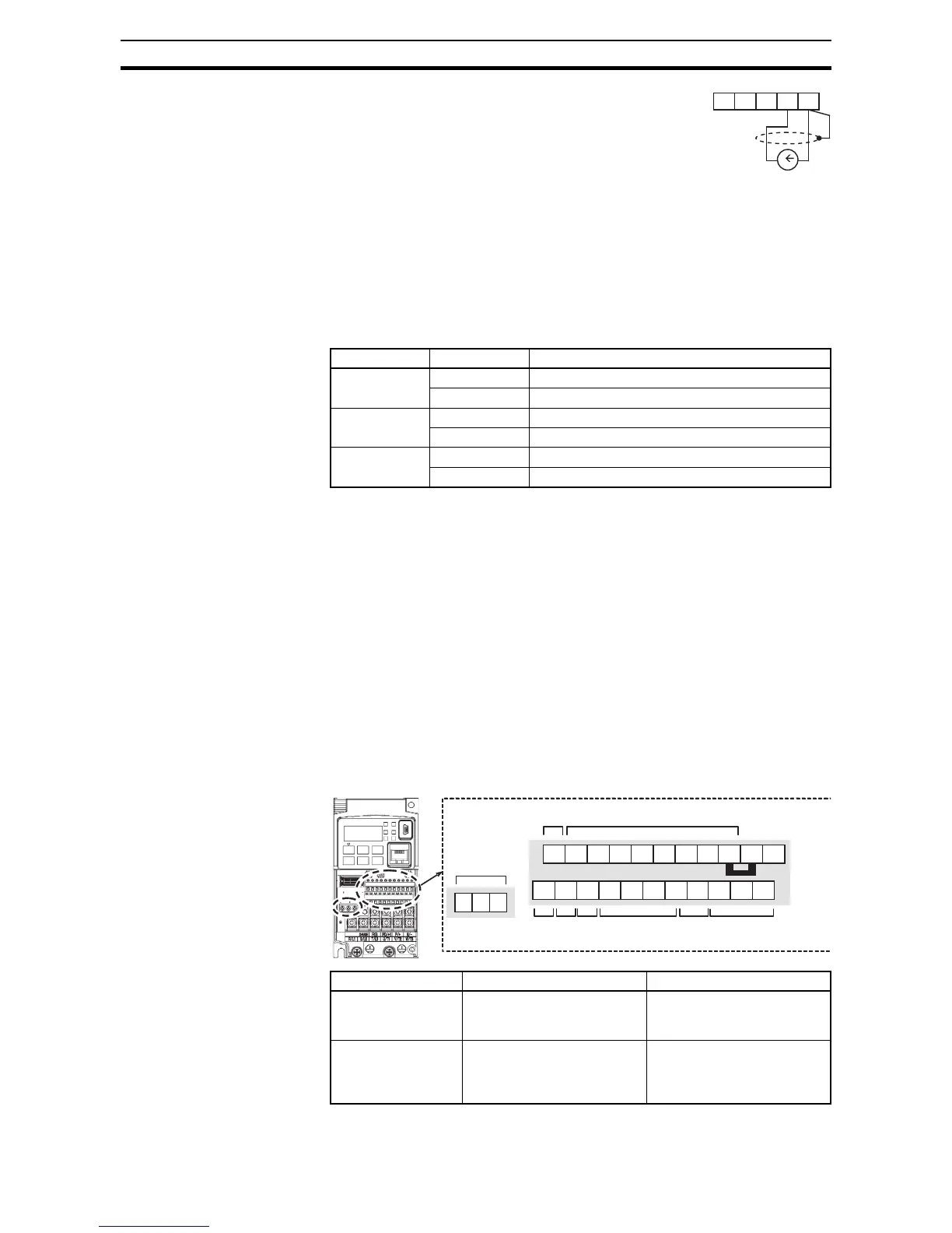
AM H O OI L
Terminal Name Description Ratings
EA Pulse train input A For frequency command,
32 kHz max.
Common is [L]
EB
(Input terminal 7)
Pulse train input B
(Set C007 to 85 )
27 VDC max.
For frequency command,
2kHz max.
Common is [PLC]
 Loading...


