223
Analog Input Operation Section 4-7
4-7 Analog Input Operation
The MX2 inverters provide for analog input
to command the inverter frequency output
value. The analog input terminal group
includes the [L], [OI], [O], and [H] terminals
on the control connector, which provide for
Voltage [O] or Current [OI] input. All analog
input signals must use the analog ground [L].
If you use either the voltage or current ana-
log input, you must select one of them using
the logic input terminal function [AT] analog
type. Refer to the table on next page show-
ing the activation of each analog input by
combination of
A005 set parameter and [AT]
terminal condition. The [AT] terminal function
is covered in "Analog Input Current/Voltage
Select" in section 4. Remember that you
must also set
A001 = 01 to select analog input
as the frequency source.
Note If no logic input terminal is configured for the [AT] function, then inverter rec-
ognizes that [AT]=OFF and MCU recognizes [O]+[OI] as analog input. In case
either (O) or (OI) is to be refered, please ground the other.
Using an external potentiometer is a com-
mon way to control the inverter output fre-
quency (and a good way to learn how to use
the analog inputs). The potentiometer uses
the built-in 10 V reference [H] and the analog
ground [L] for excitation, and the voltage
input [O] for the signal. By default, the [AT]
terminal selects the voltage input when it is
OFF.
Take care to use the proper resistance for
the potentiometer, which is 1~2kΩ, 2 Watts.
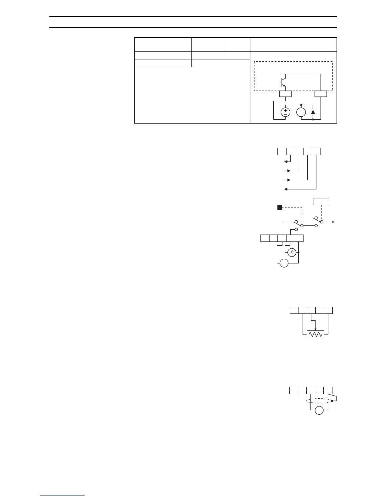
Voltage Input – The voltage input circuit
uses terminals [L] and [O]. Attach the signal
cable's shield wire only to terminal [L] on the
inverter. Maintain the voltage within specifi-
cations (do not apply negative voltage).
Valid for inputs: 11 Dedicated to terminal [11]:
Required settings:
Option
Code
Terminal
Symbol
Function
Name
State Description
RY
Inverter output
terminal circuit
CM2 11
EDM
AM H O OI L
+V Ref.
Voltage input
Current input